Where to start? Thinking of converting my mills and lathes to CNC.

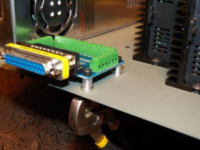
I just finished modding those little aluminum spacers a couple of minutes ago. They were the full thickness of the larger shoulder at the bottom all the way up. I turned about .050 off to make it clear the pegs sticking out of the bottom of the PCB. The base shoulder was left at the full width to make it a little more stable on the thin sheet metal below it.
100_0974.jpg
 
I found a solution to the source for the required 5V for the drivers as well as 12V for the two fans I want to add.

Here's the 20V-48V to 12V DC Voltage converter:
http://www.ebay.com/itm/150987907819?ssPageName=STRK:MEWNX:IT&_trksid=p3984.m1497.l2649

And this one is for converting 20V-50V to 5V DC:
http://www.ebay.com/itm/150987911654?ssPageName=STRK:MEWNX:IT&_trksid=p3984.m1497.l2649

With these I can just take the 36V output from the power supply and get 12V for the fans and 5V for the drivers. I won't have to add any extra cords coming into the enclosure or bulky power adapters that plug into the wall.

Speaking of fans, I got two of these 12V slim (3.1"x3.1"x.6") fans to keep the drivers cool. Each fan will be covering two drivers at a time.
http://www.ebay.com/itm/230914379043?ssPageName=STRK:MEWNX:IT&_trksid=p3984.m1497.l2649

I'll add these new bits to the post above to keep everything consolidated.
 
i'm running a bit behind i have a few projects to complete and i'll get back to your remaining files...
the voltage converters should work i have never tried them i'm sure the one for the fans will and if the 5v is a clean flat line signal it should also.
steve
 
Like I said earlier, there's no rush. I'm still waiting on that other driver to show up before I'll be able to finish the wiring anyway.

On my way back from classes today I stopped at Radio Shack to get some more wire so I will have enough to finish wiring everything up. I was almost out of green and completely out of blue. I picked up a three pack of red, black and green 18 ga wire as well as come clear speaker wire (also in 18 ga) since they didn't have any blue wire.
 
Got paid today so I put an order in at CNC4PC for a couple more parts. The UC100 cable, an E-stop switch and 6 limit switches. I'll put links to the individual parts in the consolidated parts list above so everything stays together.

EDIT: Oops. The forum software will not let me edit any posts but this last one for some reason. Until that gets sorted out I'll just put the info here for now.

UC100 cable ($129)
http://www.cnc4pc.com/Store/osc/product_info.php?cPath=93&products_id=481

E-stop switch, A9-Latch Twist-Release ($7.50)
http://www.cnc4pc.com/Store/osc/product_info.php?cPath=29_87&products_id=138

Limit switches (x6), A7, N.O. ($3.52/ea, $21.12 for 6)
http://www.cnc4pc.com/Store/osc/product_info.php?cPath=29_84&products_id=79

Shipping for all of these items was $13.25 via USPS Priority mail (cheapest option available).
 
Scored a 20" Viewsonic flat LCD monitor at a local flea market for $5 today.:)) I plugged it in and it works fine with the GX280 and it's new video card.

While I was out in town I stopped by Best Buy and picked up a full motion swing out wall mount monitor stand. Here's a link for anyone that wants to see what I'm talking about: http://www.bestbuy.com/site/Sanus--...lack/9004356.p?id=1218008113446&skuId=9004356

With this stand I'll be able to bolt the mounting bracket to the wall behind the mill and swing the monitor where it will be easiest to view it and then push it out of the way when it's not needed. The plan is to mount it high enough to keep it right above the driver enclosure and the PC which will be sitting on top of the enclosure. I'm also thinking of making a tray that will hold the keyboard and mouse directly under and in front of the monitor. I haven't worked out how I'll make the tray just yet, but I'm thinking simpler is better.
 
The CNC4PC order arrived yesterday along with the fans from ebay. The 4th axis's stepper motor and driver just arrived today (it must have come over on the FAST boat from China :rofl:) . If the voltage converters get here by the end of the week, or very early next week, I may be able to get this all assembled soon. Unfortunately I don't have time to mess with it this week since I'm in the middle of mid-terms. However, my brother will be arriving here this Sunday and visiting with me for a couple of days. He's already said he wants to help me out with the CNC project so I should be able to get a lot done. Might even be able to finish it (3 axis at least) before he leaves next Wednesday if all goes well. If not, Spring Break starts the week after next, so I'll have plenty of time to wrap up what ever doesn't get done.
 
if there is any part of the wiring diagram i sent or another part you may need help with ask
the rest is e-stop, limits, cooling fan(s) and 110ac power if your not sure about these i can draw them also but it may be a while i have a few people i'm trying to help all at the same time lol if your not sure ask i'll reply as fast as i can.
steve
 
in post number 70 the wiring diagram on the top row far right is your 4th axis 6 wire motors wiring
black A+
green A-
red B+
blueB-
the other 2 wires are not used
i'll get an xml file to get you ready for testing and the switch settings for the controllers to you soon
steve
 
here are the controller switch setting i would start with
1. on
2. off
3. off
4. off
5. off
6. on
7. on
8. on
1-3 set current to between 2.69 and 3.76 amps
4 sets current to half to reduce heating when setting still
5678 set the driver to half step or 400 steps per revolution

if you have plenty of power after tuning you may be able to use a higher microstep later to reduce motor vibration, noise and increase accuracy
steve
 
Back
Top