Where to start? Thinking of converting my mills and lathes to CNC.

My camera batteries were dead so I used my cell phone camera to take a couple of pics. The quality of the pics isn't great so I drew a couple of lines with MS paint to try to clear up the details I was talking about in my last post.

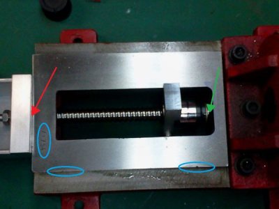
This first pic gives a good overview of a couple of things. The red arrow shows where the ball screw was protruding out the front of the base casting and not letting the aluminum motor bracket sit flush. The green arrow shows where the other end of the ball screw was hitting the base casting, which was causing the bracket mounting problem at the other end. The blue ovals are circling the areas that were dimpled or dented by the factory during manufacturing.
2013-02-20233302.jpg

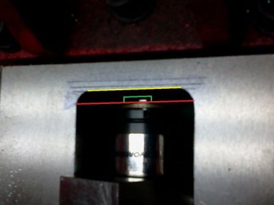
In this second pic I tried to show a close up of the clearance I milled into the base but the photo came out pretty bad. The red line is where the opening in the casting originally stopped at. The yellow line is how far back I milled it for clearance. The green line is showing where the end of the ball screw sits now that it has clearance. The gap between the green and yellow lines is about 1/16" with the motor bracket installed and sitting flush against the front of the casting.
2013-02-20233320.jpg

I'm going to change out the batteries in my camera so I can be sure to get better pics next time.
 
Last edited:
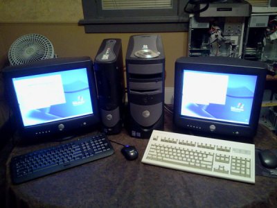
I just finished reassembling another PC tonight from the ones the school threw out. Now I have an extra backup PC in case anything happens to the primary PC. If the first one holds up ok I'll just save the second one for the other CNC projects down the road (Bridgeport mill and Atlas lathe) since they're located in another building away from the mini mill and mini lathe.

Here's the rebuilt PCs after I finally finished all the updates:
2013-02-23010706.jpg

The smaller one on the left is the better one and will be my primary CNC PC. It's a Dell Optiplex GX280 with a 3.4GHz P4 CPU, 3Gb DDR RAM, 500GB SATA HDD. I just ordered a 1Gb ATI HD6450 PCI video card for it to replace the other card I ordered that arrived DOA. Pretty much everything inside the case on this one was replaced during the rebuild, so it's practically a new machine.

The one on the right isn't too far behind technology wise so it should still be more than adequate for what I'll be using it for. It's a Dell Optiplex GX260 with a 2.4 GHz P4 CPU, 1.5Gb DDR RAM, 250Gb E-IDE HDD and a 128Mb ATI Rage Pro AGP video card. This one was built entirely with parts scrounged from three different PCs to make this one a good one.

Both PCs now have Windows XP Pro (32-bit) with all the current updates as well as all the latest drivers from Dell's website for each machine. They also both have Avast antivirus (free), Spybot Search and Destroy, Adobe Reader, Adobe Flash Player, Irfanview, and Google Chrome. Those are the common programs I always seem to use the most so I installed them all while I have them connected to the internet. Once I have all the software installed I'll be disconnecting the internet and bringing them out to the shop where they'll be staying most of the rest of their useful lives.

I'm going to take a look at the specs for AutoCAD tomorrow and see if it will work ok on these PC's. If so, I'll install that next. If not I'll just do the drawings on my laptop or my main home PC and then transfer the files to the shop PC via a USB thumb drive.

Next up will be the Mach3 demo since I've pretty much settled on using that program. I'll have to poke around their website to see what the latest version of the program is currently. I already reviewed the specs and both of these PCs meet (or exceed) the hardware requirements for Mach3 fairly easily.

The one thing I need to figure out is what I will use to convert the AutoCAD drawings to something that Mach3 can work with. So what is everyone else using for this step? Something with a free demo would be nice to check it out before buying, but I'm also looking for something simple to use and relatively cheap to buy the license for it if I like it.:thinking:
 
i use d2nc for all of my simple 2d g-code generation in mach3
if you go to this site you can see the demo videos, watch the second to last one and it will give you a good idea how easy it is to use with a dxf file.
http://d2nc.com/html/screencams.html
it also has it's own drawing features but i have never used them. the only problem i have found in the software is that it does not do islands in pockets but i have a work around for this.
d2nc is $79.00
steve
 
I got all the software (AutoCAD 2013, D2NC and Mach3) loaded onto the primary CNC PC and then defragged the HDD afterwards just for good measure. I'l start playing around with the programs a bit later to start to get a feel for using them. I also downloaded the manuals for D2NC and Mach3 to my desktop so I'll have a copy of the files for both of those programs right there on the PC if I ever need them.

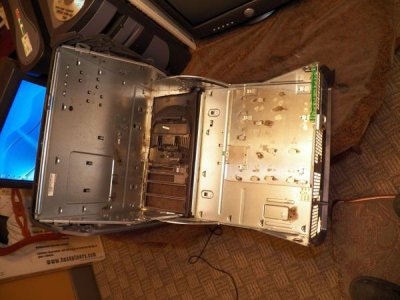
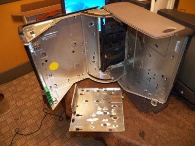
After that I grabbed an empty PC case that I'll use for housing the motor controllers, break out board and power supply and toted it out to the shop for a bit of surgery. These Dell cases are similar to the PCs I just rebuilt that open like a clam shell and have a removable motherboard tray. The problem with them was the cages for the HDD, floppy drive and CD drives were crowding the inside of the case when it was closed so I needed to cut those out to make room. I also cut off the raised screw holes on the motherboard tray so I would have a flat surface to mount everything to. After a bit of work with a 4" angle grinder this is what I ended up with.
100_0969.jpg
100_0970.jpg

After I figure out where I want everything mounted and drill the mounting holes I'll put a coat of paint on the bare metal.
 
The thought of possibly adding a 4th axis later on was still nagging at me. If there's any chance of me doing it than I should account for it in the planning stages early on while I'm building the controller enclosure mounts. Soooo.... I went ahead and ordered another driver and a slightly smaller Nema 23 for the 4th axis. I'll wait till I get the primary X, Y and Z axis completed before I make the mount for the 4th axis. That'll probably be my first CNC project after it's up and running.

Here's the driver (exact same as the other three I already have):
http://www.ebay.com/itm/271115223142?ssPageName=STRK:MEWNX:IT&_trksid=p3984.m1439.l2649

And here's the Nema 23 motor (same 4 wire and dual shaft configuration as the others, but it's only rated at 1A, 287oz.):
http://www.ebay.com/itm/270848225792?ssPageName=STRK:MEWNX:IT&_trksid=p3984.m1439.l2649

I got both of these from the same ebay vendor as the originial 3 axis kit, but unfortunately they didn't offer shipping from a US based warehouse like the first kit was. Still, since the drivers are exactly the same, I can just swap one of the ones I have on hand around while figuring where to mount them until the new one gets here.
 
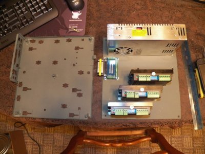
Today I made a mounting plate that I can attach to the motherboard tray. I used some threaded steel standoffs and welded them to the tray to give me some room for the attaching nuts to clear on the underside of the mounting plate. The mounting plate is just a flat sheet of 16 Gauge galvanized steel. Once I had the standoffs attached to the tray I cut the sheet metal to fit with the angle grinder using a 1/16" cut off wheel. Then I laid the drivers, power supply and BOB on the plate and shuffled them around until I was happy with the layout. I made sure to leave an extra slot for the 4th axis driver and drilled the holes for it as well. I used some small risers and positioned the BOB so the gender changer adapter will pass through the back panel on the mounting tray. Once everything was drilled and test fitted I pulled it back apart and shot both pieces with some self etching primer.

100_0973.jpg

On a side note. The picture in the ebay ad for that stepper I chose for the 4th axis appeared to be a 4 wire, but I got an email today stating that it was actually a 6 wire. Hopefully they can change it out before they ship it, otherwise I'll just have to wire it a little differently than the other three 4 wire steppers.
 
Last edited:
Hey Steve,

Is there a particular way this DB25 BOB needs to be wired? If not, do you have a recommended way to wire it up?

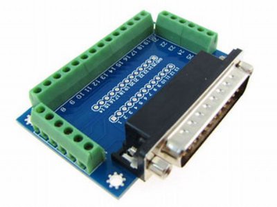
I still need to turn the standoffs down to keep them from hitting the adjoining pins that protrude from the back side of the BOB and then get some smaller screws and nuts to mount it all up. I also need to make a new back panel plate to replace the one on the motherboard tray. I want to keep everything that is wired together and mounted on the tray assembled as a modular unit. I'll use plugs where everything connects to the tray to keep it easily removable without having to unscrew a bunch of wires. The back panel will have the parallel connector, 4 motor connectors and the AC connector on it. Can you think of anything else I'll need to put on there like a 5V connector maybe?

The E-stop and main power switch will be mounted on one of the front panel covers. I may also connect some light pipes and mount them up front as well to give a visual indication of what the drivers are doing. I'm just not sure how to make a quick connector for those just yet.

The drivers are side mounted so I can put a couple of fans (to the right of them) to keep them cool. I may make a aluminum cover to help guide the air across the heat sinks as well as tie the drivers together to stabilize them a bit better. The mounting plate feels a bit flimsy with all the weight of the components bolted to it right now.
 
i need to know where you are getting your 5v for the controllers
post a pic of the board your using you have 2

on the bob:
pin 2 is x step/pulse-
pin 3 is x direction-
pin 4 is y step/pulse-
pin 5 is y dir-
pin 6 is z step/pulse-
pin 7 is z dir-
pin 8 is A step/pulse-
pin 9 is A dir-
pin 15 is e-stop-

steve
 
I'm using the simpler one that you suggested (the smaller blue one).
DB2510.jpg

I'll also be using a UC100 cable to connect it to the PC but I won't have the cable in hand till after payday at the beginning of the month. The smaller BOB doesn't have any documentation on it in the ebay ad unfortunately. I'm guessing I'll have to set the pin/port configuration in Mach3 somehow right?
http://www.ebay.com/itm/300775143431?ssPageName=STRK:MEWNX:IT&_trksid=p3984.m1497.l2649

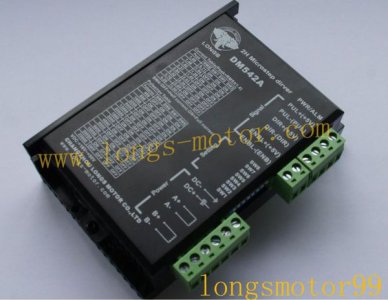
Here's the driver type I'll be using for all 4 axis (SP?).
465682210_o.jpg
From the top down the connectors are labelled:

PWR/ALM (EDIT: Never mind about this one. It's just the label for the red/green LEDs on the side)

*Signal[PUL+(+5V)
*Signal[PUL-(PUL)
*Signal[DIR+(+5V)
*Signal[DIR-(DIR)
*Signal[ENBL+(+5V)
*Signal[ENBL-(ENB)

*Setting[SW8 (Pulse/rev)
*Setting[SW7 (Pulse/rev)
*Setting[SW6 (Pulse/rev)
*Setting[SW5 (Pulse/rev)
*Setting[SW4 (ON = full current / OFF = half current)
*Setting[SW3 (Peak current)
*Setting[SW2 (Peak current)
*Setting[SW1 (Peak current)

*Power[DC-
*Power[DC+
*Power[A+
*Power[A-
*Power[B+
*Power[B-

Did you want me to post up the two tables that are shown in the pic as well? If so there's a lot of info there so it'd take a little while to get it drawn up.

For the 5VDC, I'm not sure how I'll attach it just yet. I was looking for some suggestions if you have any.

Also for what it's worth, the motors I have for X, Y and Z are rated at 3 Amps each and the smaller 4th axis motor is 1 Amp. And just to clarify, I do plan on installing limit switches as well as an E-stop switch.
 
Last edited:
in post 29 you asked about a kit is that the kit and motors you bought?
are you going to use a usb power cord to get 5v from the pc or are you going to get a 5v power supply?
I have drawn the wiring diagrams i need to find where i posted them and i will get you the entire wiring diagram
once i know the ebay item number for the motor kit you used i can give you all of the switch settings on the controllers.
i'll try to get everything to you today but we are under a severe storm watch with tornados and if it gets bad i'm unpluging everything. a storm cost me $5000 last year in lightning damage.
I'll also find an xml setup file for your mach3 so setup is easier and post it for you
steve
 
Last edited:
Back
Top