Wellllll I Guess I Am Going To Cnc My Enco 45 But Slowly

I would continue to do the wiring for at least the x axis, then bench test.
mach3 may be set to be receiving a 5v+ signal coming from the controller to ground or not ground. in that case you will not see anything checking from ground terminals and pins.
look at this drawing the 5v+ is going in on the pin not out.
Steve

View attachment 99236

My BOB pins do not match up with your drawing??
Pins are different # and tags
Bill
IMG_3618.JPG IMG_3619.JPG IMG_3621.JPG IMG_3596.JPG
 
Steve

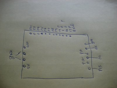
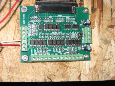
Hope you can read this as I scrawled it out in a hurry but this is what I have for BOB.


IMG_3624.JPG
 
look at the drawing I gave you again and you will see the pin numbers on the board
" 1 " is skipped but rest are the same as your board
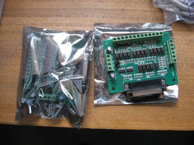
your board says P2 P3 P4 ect...
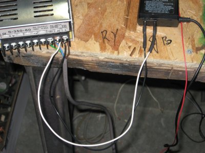
looking at your board face up and the parallel port facing you the bottom two connections on the left side are where the 5v power supply hooks up
they say + and - the 2 connections above them are not used. you have to power this bob and the 5v+ to the controllers.
run a 5v+ wire to every connection marked + on the controllers pul+ dir+ en+ thats all the jumpers you see
on the controllers in the drawing plus another one to each en+
then run pul- and dir- back to their pin numbers for " X" they are p2 for pul- p3 for dir-
" Y" are p4 for pul- p5 for dir-
"Z" are p6 for pul- p7 for dir-
all connections marked en- get jumpered together and run to pin p17
I hope this makes sense
Steve
 
Last edited:
OK sorry to be a pain and thanks again Steve, I will go back at it tomorrow morning and will wire one axis and use it to learn how to get things talking.
Here is a video I found that goes trough the wiring step by step #6 & 7 of the series and I think it covers my setup I am trying to get set up (I hope)
but I could be wrong LOL.
Good night and thanks
Bill
 
that's not your breakout board and could confuse you worse, I am sending you a pm with my phone number call me tomorrow
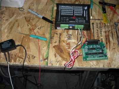
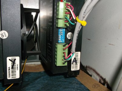
here is a pic of my power jumpers on my controllers this one is A but it is the same for all of them notice the red wire 5v+ jumpers to every connection marked +
if this is X axis then the white wire ( pul-)would go to pin p2 on your breakout board
the green wire (dir-) would go to the p3 terminal and the black (en- ) goes to p17 on the breakout board
if you click on the image you can zoom in and read the side of the controller
Dont use these switch settings for your controllers they are for a different motor on a rotary axis.
do not run the drivers without the switches set, the power supply for the "motors" connected and a motor connected, it's hard on the driver to power without the motor connected and some driver models can be damaged.
Steve


DSCF1802.JPG
 
Last edited:
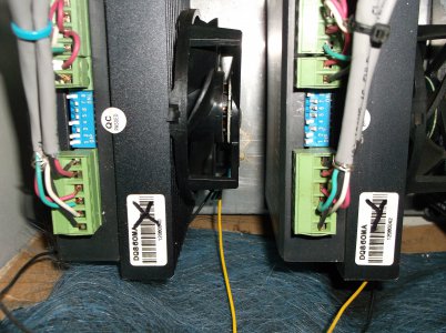
here is another view the wires i'm talking about are the top ones above the switches
notice all the red jumpers
these are also the correct switch settings for your controllers if your motors are the 1600 oz/in
DSCF1801.JPG
 
here is another view the wires i'm talking about are the top ones above the switches
notice all the red jumpers
these are also the correct switch settings for your controllers if your motors are the 1600 oz/in
View attachment 99299
Just so everybody else knows the laptop with the PCI printer port aint gunna work and thanks to Steve for all the help over the phone :beer:
So if you are thinking about a laptop it will be an up hill battle to get it working, I wint down to the local PC repair shop and the guy gave me 4 desktops 2 monitors ande 1 keyboard from his scrap pile, the first one I plugged in fired right up but monitor craped out after a few minutes, tride #2 monitor fired right up with a brand new install of win XP media edition and Steve got me on the right track with wiring and setup on Mach 3
So I figure I should have motor testing and running tomorrow:aok::chemist:
Bill

I'm setting up a system using a laptop with electronics the same as yours. I don't have a printer port on my laptop so I'm using a UC-100 fed from a USB hub The breakout board is powered by the hub. The hub gets "signal", for lack of a better word, from the laptop. Check out my build here on the Precision Mathews forum. http://www.hobby-machinist.com/threads/taking-the-cnc-plunge.24858/page-5#post-291558. Steve's been helping me out as well. Wouldn't be where I'm at without him and others keeping me headed in the right direction.

Tom S

Steve & I found on investigation of my laptop (HP ZV6000) that I could not change the bios to turn on the printer port and my DB25 adapter was a PCI slot model so I think it is a laptop specific problem.
I may fuss with it after I get my freebee E machines operational, I like the idea of the laptop for the space it wont take up and it can be closed up when not in use.
Your cabinet looks real nice (im jealous) I ended up with a large aluminum electrical panel to put my controllers Etc in that is set to hang on the wall.
Bill

Thanks for the compliment on my cabinet. The pictures don't show it but there are a "lot" of extra holes in the mounting plate. Took me several iterations to get the layout where I wanted it.

Wouldn't be where I'm at without help from this forum. Steve, Jim, Jay and many others have helped get me to where I'm at with my conversion. Many thanks to them.

Tom S
 
Back
Top