Tool and cutter grinder build

OK, here are a few links with some info on the motors and such...

This page says the shaft is 15 mm - http://www.masonclan.org/Machine Shop Mods/LatheMotorMods.html

From this forum - http://www.hobby-machinist.com/showthread.php/14877-sewing-machine-motors?highlight=BKToys

Some info on wiring mods if you want to mount the controller remotely, though in this application, maybe not? - http://home.comcast.net/~ajawam3/swarf/maxnc.html

All the users say the torque is pretty even across the RPM range as their a brushless servo motor and I suspect the controller works like a VFD.

Seems like a lot of good things going for it, so maybe if your even considering it, start squirreling away your pennies now. :thumbzup:

Mark
 
Really good stuff Mark, thanks for posting all of this. Between my notifications from this thread and my Yahoo Groups updates I'm getting stereo! :))
 
As of right now, it is at the top of my list


OK, here are a few links with some info on the motors and such...

This page says the shaft is 15 mm - http://www.masonclan.org/Machine Shop Mods/LatheMotorMods.html

From this forum - http://www.hobby-machinist.com/showthread.php/14877-sewing-machine-motors?highlight=BKToys

Some info on wiring mods if you want to mount the controller remotely, though in this application, maybe not? - http://home.comcast.net/~ajawam3/swarf/maxnc.html

All the users say the torque is pretty even across the RPM range as their a brushless servo motor and I suspect the controller works like a VFD.

Seems like a lot of good things going for it, so maybe if your even considering it, start squirreling away your pennies now. :thumbzup:

Mark
 
Today I finished up the micrometer
Micrometer dial markings.jpg

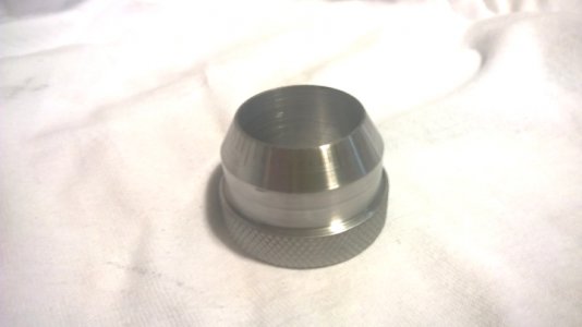
I don't know what happened to the photos of engraving the lines on the micrometer, but they got lost somewhere. :dunno: Oh well, I have shown engraving lines before, but since this micrometer has a 30 degree angle on the end , the compound had to be set to 30 degrees to engrave the lines. I will stamp the numbers later. These lines came out perfect and sharp but they are only .010" deep and hard to see unless the light is good. They will have to do though as it took two tries and about 2 1/2 hours to engrave them. they are the best I ever done, just not deep enough. there are 50 lines as the micrometer is .050" per turn.
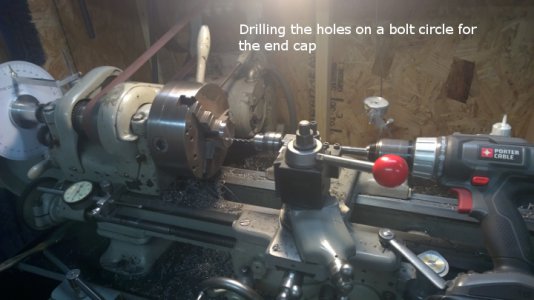
drilling end cap mounting holes.jpg Here I am drilling three holes 120 degrees apart in the flange to mount the micrometer barrel on the base. Once again using my drilling jig for the lathe. My degree wheel is used to set the spacing. ( photo at end)
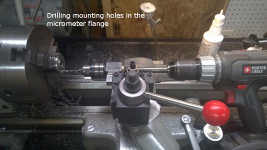
drilling micrometer flange.jpg I also used the drilling jig to drill the three holes in the flange of the end cap for the micrometer bar.
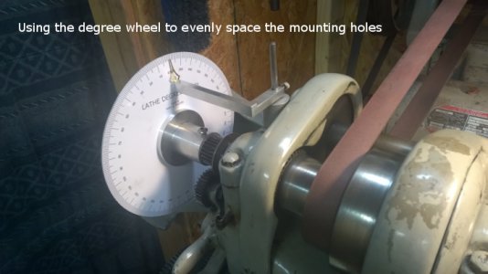
degree wheel for hole spacing.jpg This photo shows the degree wheel setup to space the holes 120 degrees apart.


As I need a CRS bar 3/8" x 1 1/4" x 19" long and can't find one locally, I will be moving on to another part of the process until I locate a bar.

I started machining the sliding base which is the bottom half of the work head. It slides on the micrometer bar and holds the tilting work head. I chucked a piece of 2" x 2" x 4 5/8" bar stock in the 4 jaw chuck.
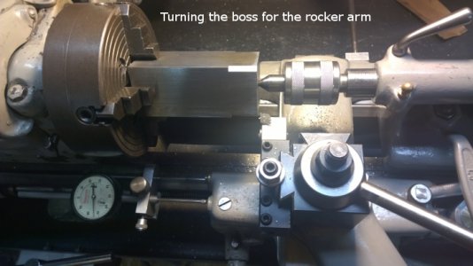
turnig boss for rocker arm.jpg There needs to be a boss ( 1" long and mine will be 1.740" diameter ) on the end for the rocker arm. Refer to Drwg no. G2 & G4 in the prints. I am making this a little bigger and heavier than called for just because that is the material I have. This photo and the next shows turning that boss.
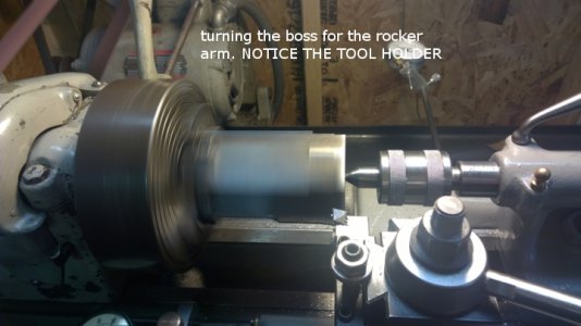
turning the boss for the rocker arm.jpg Notice the tool holder I am using to turn this. My new made tangential tool holder. I cut .050" per side cut and the tool did not slip on this interrupted cut ( I must have done something right :)) )

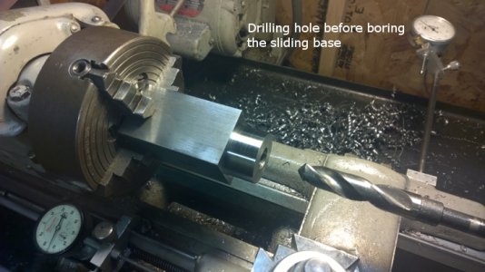
drilling sliding base.jpg The next step is to drill the hole to 3/4" so I can get my 5/8" boring bar in it.
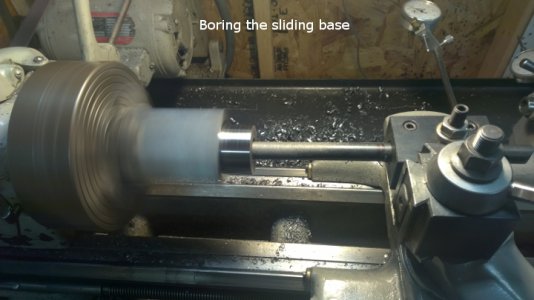
boring the sliding base.jpg This shows boring the hole. All these steps needed done on the one setup to insure the concentricity of these surfaces. The other end gets a short boss but it will be done in the three jaw as it can be a few thousandths off and it won't matter. That boring bar has a lot of spring in it so it will take a lot of passes to get a straight hole. I will use a brake hone once I get close to finish it because it must be a perfect sliding fit on the micrometer bar.


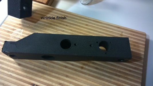
I decided since the base ends are basically finished to paint them with the wrinkle finish. ( I forgot what a b***ch that stuff is to work with.) I painted them in the kitchen and baked them in the oven to get a good wrinkle. Needless to say ...... the Mrs. ain't happy :angry:. The house is full of fumes and she is hiding out in her room. Oh well.... she'll get over it ( and I took her out and bought her a new coat before I started to paint so she can't really complain about a few fumes :rofl:. ) I call that good planning.:rofl:


These two photos show the wrinkle finish. It is hard to see but after an hour in the oven at 225 degrees, it wrinkled really well. I got a few nicks here and there because with every surface painted and handling with wire hooks to hang them in the oven, I bumped the paint a couple times ( these parts are heavy). Once the shiny goodies are added , no one will notice the paint flaws. I ain't about to try and do them over. It looks just like the black wrinkle finish on a Starrett level or indicator body. I think it adds a lot of class.
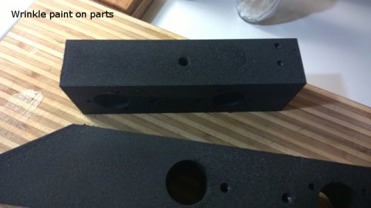
wrinkle finish.jpgwrinkle finish 2.jpg

Depending on the weather tomorrow, I will resume working on the work head base.

degree wheel for hole spacing.jpg drilling end cap mounting holes.jpg drilling micrometer flange.jpg Micrometer dial markings.jpg turnig boss for rocker arm.jpg turning the boss for the rocker arm.jpg boring the sliding base.jpg drilling sliding base.jpg wrinkle finish 2.jpg wrinkle finish.jpg
 
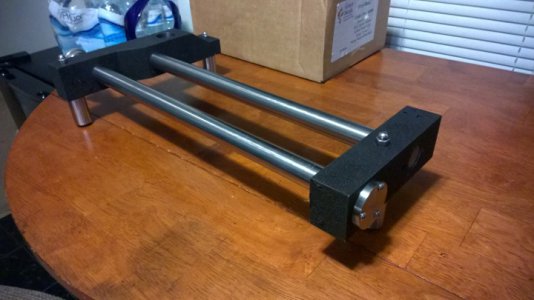
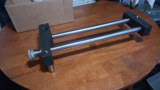
Here's a couple photos of the painted base assembly

painted base assembly.jpg
painted base assembly 2.jpg

Came out well. I am satisfied with it so far.

painted base assembly 2.jpg painted base assembly.jpg
 
As usual; WOW! Here I go again building another "Must have" folder for future use (right next to Bill's build). It runs against my grain to throw anything away so I have boxes and boxes of abused and unloved end mills. Needless to say I will follow this one as well.

The Mad Modder link is interesting. He also makes good use of a CNC mill. (Cheater.)

And as always, thanks for taking the time to document the build. (That's an art in itself.) You give ham-handed hacks like myself a glimmer of hope. :rofl:
 
Yesterday was spent looking for metal I need to build my grinder. I couldn't find it at the local metal supplier. He carries mostly HRS and I want all CRS. I got a piece of 2" x 2" x 6" CRS for the work head ( that stuff is $25 / foot :shocked:). My buddy and I stopped at a friend's production shop on the way home and when he found out what we were looking for, he said "how much you need?" He gave me 2 feet of 1" x 3/8" CRS, 2 feet of 3/8" square CRS, 18" of 1 3/8" CRS round bar, and some 1/8" plate that I needed. In exchange I told him I would make him 4 machinist jack's ( I had made him a couple before.) and he gave me 2 feet of 1 1/2" CRS round bar to make them ( it only takes 6") I made his jacks this afternoon.

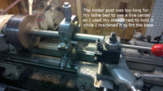
Now my grinder is going to start to get different than the prints. ( Prints, what prints, :nuts:, who needs prints :rofl:) . The first big change was to make my bed 19" long instead of 12". The prints call for the motor post to be 1 1/4" diameter. I chose to beef mine up to 1 3/8" diameter and 14" tall instead of 11". This is going to make my grinder much larger and heavier than what the prints call for.

machining motor post.jpg This photo shows machining the end of the 1 3/8" diameter down to 1 1/4" diameter for two inches to fit the base. The bar was too long for my lathe to use a live center , so I used my steady rest to hold it while I turned the end.

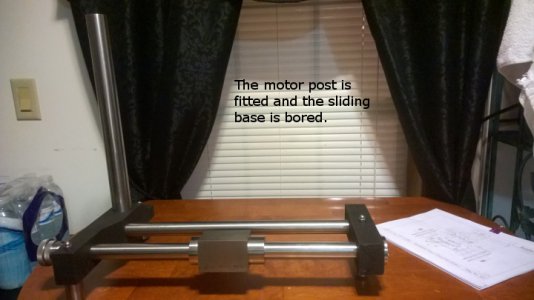
Base unit 10.jpg I finished turning and boring the sliding base unit that holds the work head. I should have not taken that last ghost pass, as I got a little too much slide. :panic: I thought maybe I had just scrapped a $25 piece of steel. It came out about .001" oversize. I think it will be fine because when grinding the base is locked to the bar. The lock will still hold it tight to the bar.
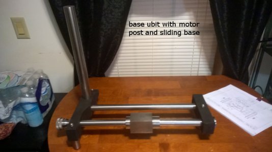
base unit 11.jpg This is the base , motor post, and sliding base. I chose to make the sliding base from 2" x 2" square CRS , instead of the 1 5/8" square the print calls for. Again, this will make things a little more heavy duty. I find changing all these parts has a trickle down effect. I have to change all the dimensions of the associated parts that attach to the base also. To keep up with the changes, I am now drawing a complete new print of my own for each part and including all the changes. This way , I will have prints to match what I build and to share with others who want to build a t & c grinder. This requires many hours of work in itself.
:think1: This thing should start to get interesting pretty soon.

Base unit 10.jpg base unit 11.jpg machining motor post.jpg
 
I like the changes you are making, as I think this will make the grinder more stable and robust. This is going to get interesting! :)
 
Back
Top