Tool and cutter grinder build

I too like the idea of a bellows on at least the front bar, but when I priced them they gave me pause. Probably will just pony up for it anyway. I like the shield idea for the screw.

Things that make you go hmmm... ;)

McMaster carr has the bellows but WOW $$$$ . I looked at a bellows for shock absorbers on cars and trucks. They are the same but heavier ( thicker). They work, but take up a lot of travel. Vacumn hose is lighter and will also work for bellows.
 
I too like the idea of a bellows on at least the front bar, but when I priced them they gave me pause. Probably will just pony up for it anyway. I like the shield idea for the screw.

Things that make you go hmmm... ;)

I have been doing a write up on my computer also with all the pics. I have part 1 done which is up to the present and am starting another file called part 2 ( imagine that). It is in PDF form and is a little more than 6 Mb. I can send it to you if you like. I don't know if it can be posted somewhere on here or not. ( maybe not needed cause this thread is here). It may help when you build yours.
 
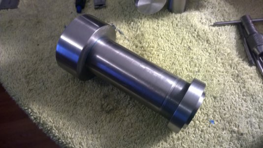
Finished up my tool holder today. I am not happy with it. It is usable , but too far from perfect. I threaded the spindle and made a nut for it. The threas are 1.5"-28.
toolo holder27.jpg The end (you can just see it) has the threads turned off to 1.450" diameter. This is to be able to use the swinging head stock linkage.
tool holder26.jpg This is the spindle and nut installed. You can see the smooth area for the linkage.

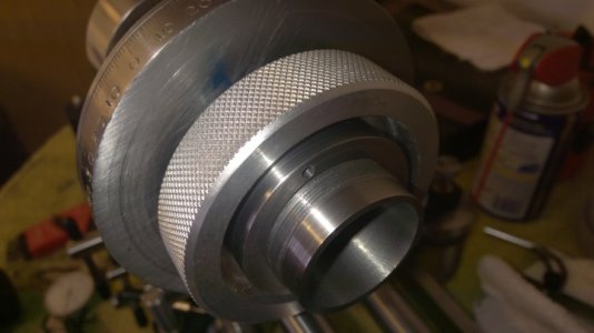
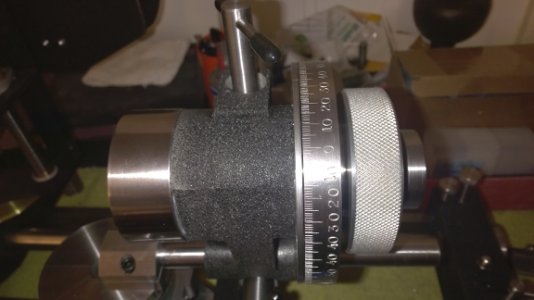
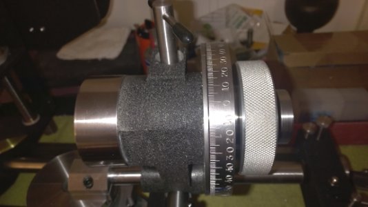
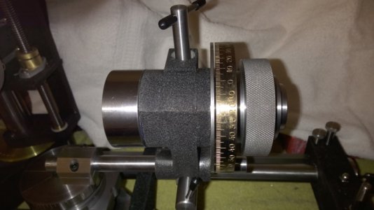
tool holder25.jpg And the finished tool holder. The problem is if I tighten the nut to remove all end play, there is a tight spot when turning the spindle. If I leave it loose enough to turn freely, there is .002" end play. I don't like the end play. I am not sure what to do about it yet. I am thinking of a nylon spacer about .010" thick where you see the little space between the index shield plate and the index plate. This space is caused by the aluminum housing sticks out far enough for the index plate to ride against it ( a bearing surface of .200" wide). This was to have minimal surface contact hoping to avoid this problem. I faced and bored the housing for the spindle together so the front is square with the bore. when I turned it around to face the back side, I tried to indicate it as close as possible , but that is hard to judge. I believe the rear face is a hair out of square causing this problem. It would probably wear in in time and adjustment would fix it, but it still bothers me.Any way , a thin nylon spacer may help. Tomorrow is another day. I will worry about it tomorrow. tool holder26.jpg tool holder25.jpg
 
Bellows work great, the problem is they are expensive to purchase.

Thus, make them.

1) Procure some rugged cloth. Ex. Dennum, Light canvas, oil cloth etc.
2) Cut out several disks (for a 1/2 dia screw ) two inches in diameter.
3) Cut or punch an approx. 3/4 dia. hole in the center of each.
4) Pair up the disks, and sew the center hole together of each pair.
5) Then sew the outside together of two pair.
Continue until the assembled length is sufficiend for current demands.

Then figure out how to mount it in your situation.

Restorer
I have a guide for making them. I have been entertaining the idea of making them.
 
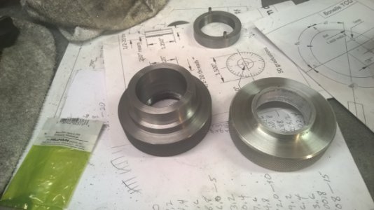
I am happy again with my tool holder. I finally figured out the problem was too many parts. The index wheel the hand wheel and the lock nut. there was too much room for error and movement. I scrapped the aluminum hand wheel and made a one piece steel one.
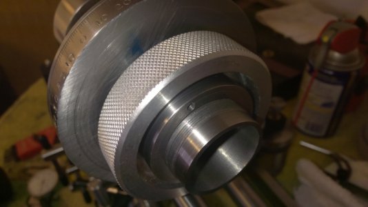
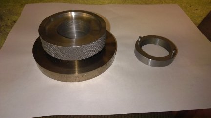
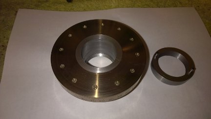
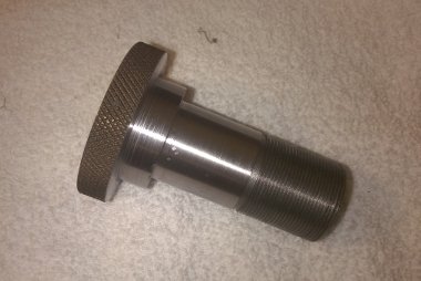
hand wheel comparison 2.jpg Here you can see the difference. The step on the hand wheel is for the index wheel. It is 2.004" diameter. The index wheel was bored out to 2.000". The hand wheel put in the freezer, the index wheel went in the oven at 500 degrees. they fell together and became one piece when cooled. ( Thank you Bill Gruby - this was an idea I got from following the master). The new hand wheel is also threaded for .375" into its bore. once screwed on to proper location, the lock nut holds it there.

tool holder hand wheel30.jpg back view tool holder hand wheel.jpg
this is the two pieces put together.... foorevveerrr.

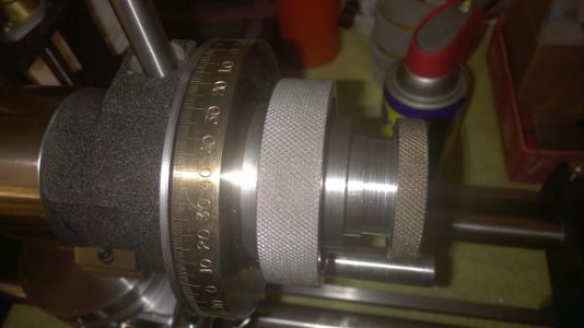
tool holder 30.jpg This is the assembled tool holder. I also put a plastic washer between the spindle nose and housing and another between the index wheel assembly and the housing. They are .010" thick and made of a tough polystyrene ( I cut them from a couple of lids my wife had in the cup board for some fancy containers). They keep the two metals from rubbing together. the tool holder turns very smooth and there is no detectable end play.

Heating the index ring changed its color to a brassy look. I kind of like it, but am considering machining the lines and numbers off and redoing them. I would only put marks every 5 degrees and use a vernier like I am going to do on the rotary base table. I am still undecided. The 5 and 10 degree marks are perfect. The one degree marks are mostly good , but a few are a tiny bit off. They are still a good guide to judge by. We'll decide this later.
 
Today I made the draw bar for the 5 c collet. It has a .750" through hole ( which will probably never get used, but better safe than sorry).
tool holder draw bar.jpg The threads are 1.041"-24 to match the internal threads on the collet.

draw bar in tool holder.jpg This is the draw bar in the tool holder. I also put a small brass key ( 1/8" diameter ) in the spindle to fit into the key way in the collet. The tool holder is now complete and I am glad, as it has been the hardest part of this whole build so far. I still have to make two vernier scales for this work head and then on to the spindle and pulleys.
 
Back
Top