Tool and cutter grinder build

I made a little more progress today. I needed a plate 4" diameter and .125" thick. The only thing I had was 5" diameter and .315" thick. It took a lot of turning , but I cut it down to size.
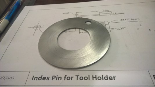
index cover plate.jpg A couple hours in the lathe and I got my plate. After I went to all the trouble to make this plate, (it was in the original design), I discovered I don't really need it, as I changed the design of the tool holder, but am going to use it anyway so my efforts are not wasted. :rofl:
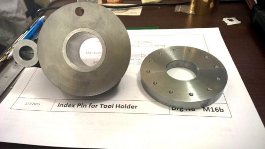
index plate.jpg I also set the index plate up on the rotary table and drilled the indexing holes.

The bearing faces on the tool holder body seem to be a couple thousandths out of being perpendicular to the bore in the body. I am sure there is probably a way to set it up and machine them square, but I can't think of it. So, I guess I will hand scrape them square to have the accuracy of "no" end play in the spindle.

index plate.jpg index cover plate.jpg
 
Today was spent on finishing details. They take a lot of time but must be done as perfect as you can do them to yield the desired accuracy in the end.

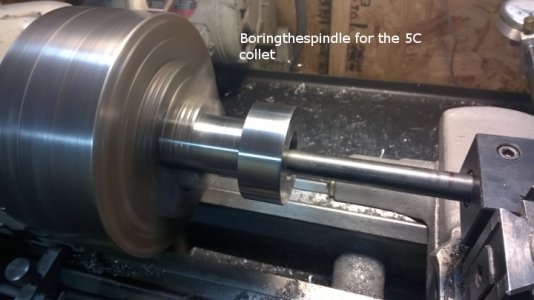
boring the spindle.jpg The spindle was chucked up in the 3 jaw chuck for boring. The TIR was .003". To improve this a .002" shim was put under the offending jaw, making the TIR of the spindle under .001". Once dialed in the spindle was bored to 1.251" for the collets and a 10 degree taper cut in the front to an O.D. of 1.485". The nose on the collet was shortened to 1" long prior to boring.


This is a trick I was taught years ago. I keep loose feeler gauge leaves for this purpose. My 3 jaw usually clamps up to .001" to .003" run out. Sometimes by putting a small feeler gauge leaf under a jaw the TIR can be reduced dramatically.


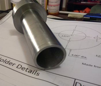
rear of spindle.jpg The finished spindle wall is approx. 1/8" thick.
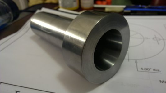
spindle bored for collet.jpg The front nose has the 10 degree angle for the 5C collet.

I chucked up the tool holder body and spent some time "inspecting" it with a dial indicator. Indicated the bore while in the chuck until it was as close to straight as I felt It would get and skim cut a few thousandths of the front face, turned it around and repeated the process on the other face. This improved the fit, but now I will hand scrape these faces to be as close as possible to parallel.
The spindle still has to be threaded on the rear end and keys added for the index plate and hand wheel. These key ways will be done on the lathe.

boring the spindle.jpg rear of spindle.jpg spindle bored for collet.jpg
 
Thank you for sharing the build with this group. I would like to get a copy of the plans of this machine when finished. You are truly a talented machinist.:talktogod:
 
Thank you for sharing the build with this group. I would like to get a copy of the plans of this machine when finished. You are truly a talented machinist.:talktogod:

No problem.Just remind me as there are too many requests for the plans to remember.
 
Mark
Nice, very nice. It will not be long now.
Looking good
Nelson
 
Last edited:
Great day today! I am almost done with the tool holder. I am waiting on some material to finish it up.:victory:
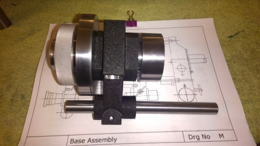
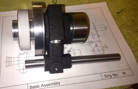
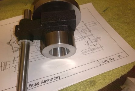
toll holdertemp assembled.jpg The tool holder is close to done. I still have to thread the end of the spindle. I gave the body another coat of paint to freshen it up. now that most everything is done.

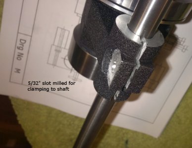
tool holder temp assembled 3.jpg I cut a slot for the bottom clamp. I will make the clamp bolt tomorrow.

tool holder temp assembled 4.jpg Cut a bar for the mounting to the base unit.

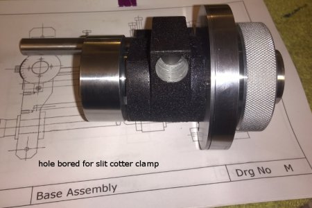
tool holder temp assembled 5.jpg I bored the hole for the split cotter clamp for the spindle.
tool holder temp assembled2.jpg

I still have to engrave the degrees markings on the index dial. I have to do the same on the rotary table base also. I am waiting for a warmer day as the two will take most of the day to do.

I didn't think I was going to like the tool holder.Due to all the changes, I built it kind of "by the seat of my pants" machining, but I am pleased with the outcome now that I see it close to completion. I still have to make the index pin, but it will be made of brass. (gotta have some brass on everything for a little "bling"):rofl:

toll holdertemp assembled.jpg tool holder temp assembled 3.jpg tool holder temp assembled 4.jpg tool holder temp assembled 5.jpg tool holder temp assembled2.jpg
 
Mark
Nice, very nice. It will not be long now.
Looking good
Nelson


Thanks, it is getting there. I am still deciding on a motor. I am also looking at big changes for the wheel head. I am going to "beef" it up some and looking at changing the elevation mechanism to either an acme screw or a ball screw. Cost is not much different, So I am leaning towards the ball screw.:makingdecision:
 
Someone help me understand something. This machine is using mostly split cotters to clamp various parts in place.In the prints , there are small "slots" milled in the back of the split cotters and a set screw with a lock nut screws into the body to locate in the slot. I fail to understand the purpose of this. It can't be to stop rotation as they can't rotate once in place. I have other things with split cotters and they don't do this. To me this seems like "overkill". Is there a purpose?

Opinions wanted......:dunno:
 
In my opinion they must be there for assembly. As you state, they can't rotate once the shaft is in place. I've seen this done on other things with split cotters as well. I figure if you can get it together without them, you probably don't need them. If you planned on having it apart a lot, I guess they would probably save some time on assembly.
 
Mark
Do you have a picture of that cotter? I've read different articles and do not remember a set screw on any of them.
Nelson
 
Back
Top