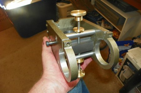
My cotter worked excellent. Holds the wheel head securely and the spring pushes it apart when the cotter is loosened. I find it easy to make the cotter separately. I measured or calculated the distance of the interference and use an end mill to cut the relief for anything up to 1" in diameter. A lot of folks prefer to clamp the material in to the piece and bore them together. I guess it is preference. If I have several cotters the same size, once the mill is set up , I can just crank them out in no time.
-
Welcome back Guest! Did you know you can mentor other members here at H-M? If not, please check out our Relaunch of Hobby Machinist Mentoring Program!
You are using an out of date browser. It may not display this or other websites correctly.
You should upgrade or use an alternative browser.
You should upgrade or use an alternative browser.
Tool and cutter grinder build
- Thread starter Mark_f
- Start date
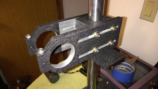
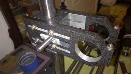
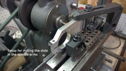
Today I got busy on the wheel head assembly. As I am building this part, I realized I way over engineered it. I had it designed with gibs and adjusting screws, complicated gides for the arms and more stuff. After building it I realized, this thing is really sturdy and all that stuff is not needed. This wheel head is a beast, even made from aluminum. The first thing I did today was mill all the slots in the arms that hold the spindle. This required some wierd setting up on my little Burke mill. this photo is the setup for milling the slots in the arms. I made marks on the table for location and start and stop points. This was to make everything exactly alike.
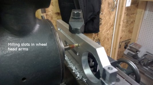
After milling the slots, all the bolt holes were laid out on the elevation block and drilled and tapped.
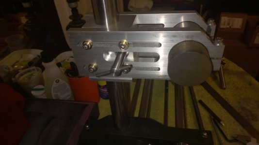
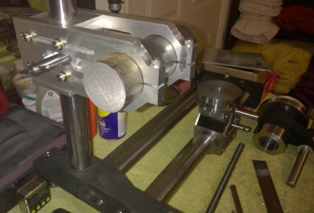
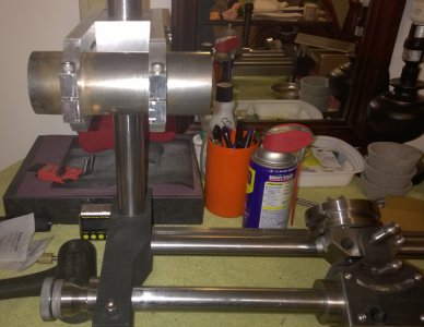
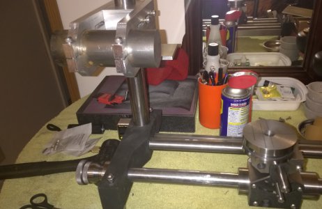
These photos are the temporary assembly to check fit. Now they are baking in the kitchen oven after applying the wrinkle finish. I will post pics of the painted assembly later tonight. I will be using all stainless steel bolts as they look so much better.


After milling the slots, all the bolt holes were laid out on the elevation block and drilled and tapped.


These photos are the temporary assembly to check fit. Now they are baking in the kitchen oven after applying the wrinkle finish. I will post pics of the painted assembly later tonight. I will be using all stainless steel bolts as they look so much better.
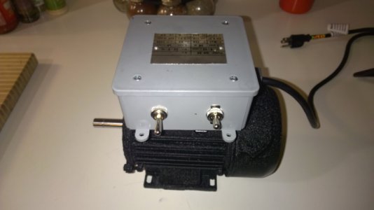
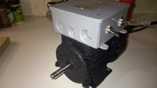
Ok,,,, I got my motor for the grinder today. It is all set up to use and works fantastic. Runs smooth and quiet. Now I will tell you about it. It was such a crazy idea and I have been ridiculed ( elsewhere on the net) for even suggesting this, but I was fairly sure I could pull it off. The ideal motor for the grinder should have adequate power, 3450 rpm, lots of torque, and be small in size to be light weight. In searching for quite a while I ran onto the solution on eBay. A CHINESE WATER PUMP!! It is small. The housing is aluminum, the end bells are cast iron, it has ball bearings, it is 3450 rpm, it is 1/2 HP, it has copper windings, and it is light weight. Sounds like the perfect motor. Soooo... what is wrong with it you may ask? ..... Well, it has a pump built on to the front end. The end of the motor and pump are cast as one piece. It is NOT reversible and runs the wrong direction. Minor inconveniences, but important ones. It is a good thing I have a lot of experience with rewinding and rebuilding AC and DC motors.
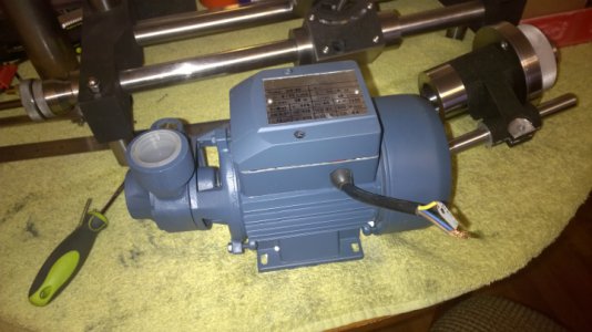
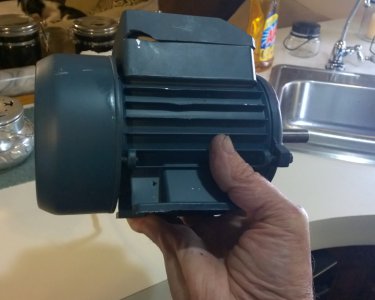
You can see how small it is for a 1/2HP motor , it is really small as I am holding it in one hand.
This is the pump and motor. My first order of business is to tear it apart.
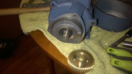
Now out to the shop and cut the pump off in the band saw.
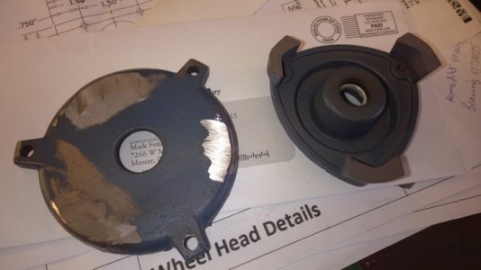
There, now the front looks like any other electric motor. Firs problem solved.
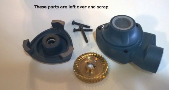
These parts are now scrap!
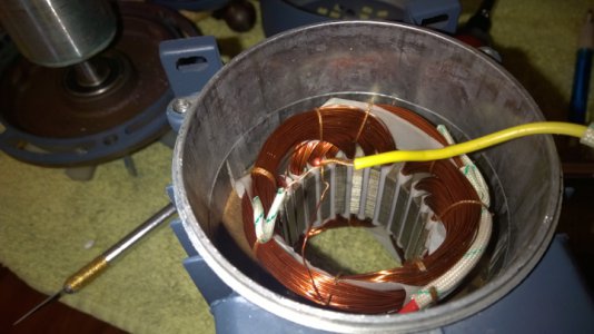
Next , I lifted the one lead that is common to the run winding and the start winding and cut them apart. You can see the two windings welded to the yellow lead here. I cut the start winding loose and attached it to it's own (white) lead.
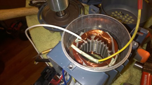
Next, I tied the leads back down with nylon cord and coated them with a half a bottle of clear fingernail polish to secure everything in place. ( LMAO, my wife is still trying to find her fingernail polish).
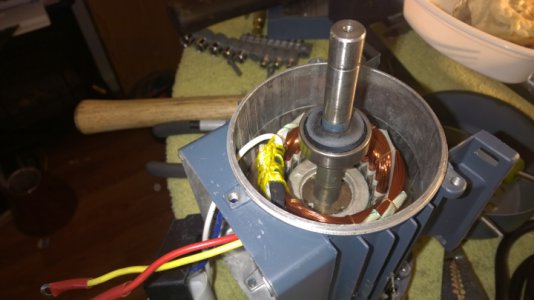
Now I have four leads coming out instead of three and the motor is now reversible. I added a start/ stop switch
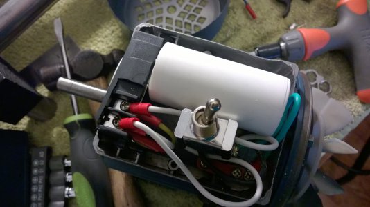
The motor is ready to go and it only cost me $30.
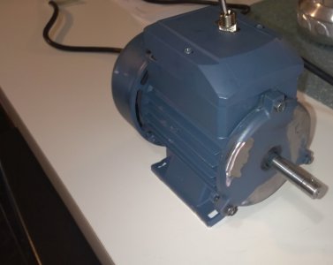
It will get a coat of paint to spiffy it up.

You can see how small it is for a 1/2HP motor , it is really small as I am holding it in one hand.

This is the pump and motor. My first order of business is to tear it apart.

Now out to the shop and cut the pump off in the band saw.

There, now the front looks like any other electric motor. Firs problem solved.

These parts are now scrap!

Next , I lifted the one lead that is common to the run winding and the start winding and cut them apart. You can see the two windings welded to the yellow lead here. I cut the start winding loose and attached it to it's own (white) lead.

Next, I tied the leads back down with nylon cord and coated them with a half a bottle of clear fingernail polish to secure everything in place. ( LMAO, my wife is still trying to find her fingernail polish).

Now I have four leads coming out instead of three and the motor is now reversible. I added a start/ stop switch

The motor is ready to go and it only cost me $30.

It will get a coat of paint to spiffy it up.
I got the screw and nut for elevating the wheel head on the grinder
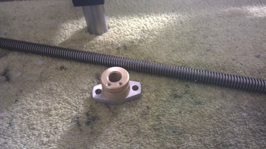
The screw is an acme 1/2"-10 lead screw. I will have to machine the ends and cut it to length. The nut is brass and adjustable for zero back lash. They were really reasonable. I got them on eBay for about $30 for both.
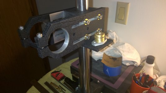
This is where the nut will mount on the wheel head. If it is warm enough in the shop tomorrow, I will start the needed brackets to mount these.

The screw is an acme 1/2"-10 lead screw. I will have to machine the ends and cut it to length. The nut is brass and adjustable for zero back lash. They were really reasonable. I got them on eBay for about $30 for both.

This is where the nut will mount on the wheel head. If it is warm enough in the shop tomorrow, I will start the needed brackets to mount these.
B
Bill Gruby
Forum Guest
Register Today
Rounding third and headed for home Mark. Great work.
"Billy G"
"Billy G"
Awesome work, Mark! That thing is really coming together. I'll bet when people see it they'll be looking for a manufacturer's stamp on it.
Thank you, it is going better than I thought it would.
B
Bill Gruby
Forum Guest
Register Today

