-
Welcome back Guest! Did you know you can mentor other members here at H-M? If not, please check out our Relaunch of Hobby Machinist Mentoring Program!
You are using an out of date browser. It may not display this or other websites correctly.
You should upgrade or use an alternative browser.
You should upgrade or use an alternative browser.
Showing off my RC model boats
- Thread starter Ken_NJ
- Start date
- Joined
- Feb 13, 2023
- Messages
- 63
Back around 1990's, Dumas Models did make some fiberglass hulls. They made two Scarab hulls. One a 45 inch S Class and another a 55 inch hull. These days they are hard to come by and back then would have been powered by model airplane style gas engines, today you can do electric. What I have is a 45 inch hull that was given to me by my machinist friend Charlie, thank you Charlie. Occasionally I'll look on eBay or Craigslist and can find one for sale. The 55 inch hull is a closer match to the real KAAMA. Since I wanted to model the KAAMA, I went with using the 45 inch hull as my model even though it is not that close of a match. The scale turns out to be 1:8.5 so a six foot person would be about 8 inches tall.
Back in the 70's and 80's there was an offshore powerboat race that ran out of Point Pleasant NJ called the Benihana Grand Prix. It was a 300 mile offshore race that ran from Point Pleasant to Seaside to Long Island to Sandy Hook and back to Point Pleasant. Must have been grueling for the crew's bodies pounding in those boats. Betty Cook was and offshore powerboat racer and KAAMA was her team. The first woman in the sport and she won many championships. She died in 1990 at the age of 70 from cancer . A very inspiring woman.
I'll post pictures that I took from my boat later of this race.
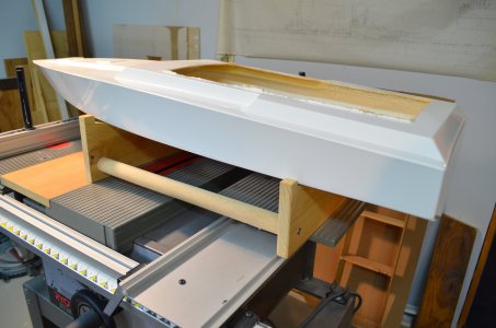
This is the bare hull.
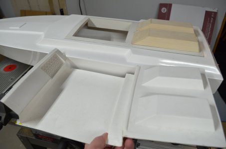
The kit cockpit which I will not be using. And my work in progress cockpit.
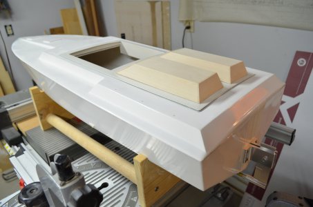
Start building the new cockpit.
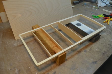
The underside.
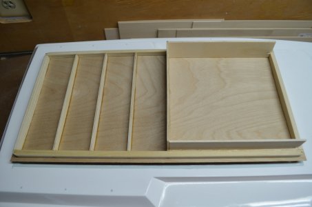
Opening cut. The top skin is 1/32 model aircraft plywood, nice stuff.
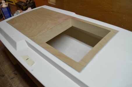
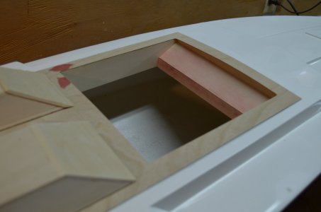
Engine covers.
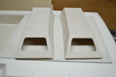
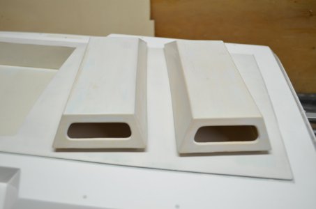
Cockpit progress. Fiberglass resin on everything. Dash in place. Still have to adhere the engine covers.
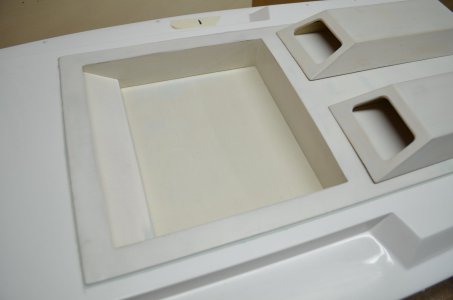
More fiberglass work. These two simulated hatch covers have to go.
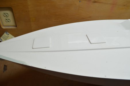
Removed.
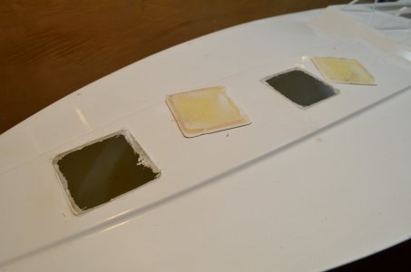
On the underside of the deck (not seen) I have plywood covering the openings. To hold them in place I have these two straps with bolts sandwiching them to the underside of the deck while the resin cures.
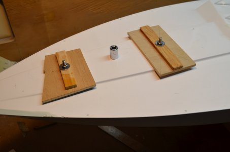
Straps removed.
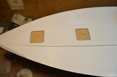
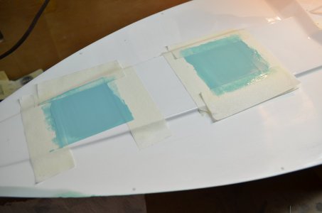
Multiple coats of resin filler.
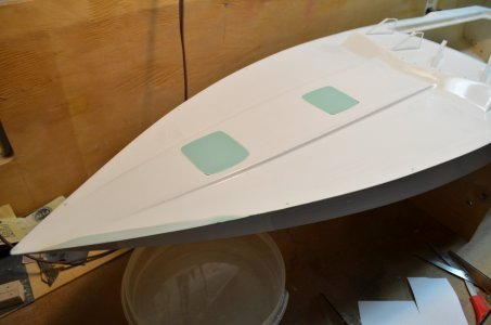
Sanded down. Later when you see the deck painted you will not be able to notice these patches.
Plenty more to come.
Back in the 70's and 80's there was an offshore powerboat race that ran out of Point Pleasant NJ called the Benihana Grand Prix. It was a 300 mile offshore race that ran from Point Pleasant to Seaside to Long Island to Sandy Hook and back to Point Pleasant. Must have been grueling for the crew's bodies pounding in those boats. Betty Cook was and offshore powerboat racer and KAAMA was her team. The first woman in the sport and she won many championships. She died in 1990 at the age of 70 from cancer
I'll post pictures that I took from my boat later of this race.
This is the bare hull.

The kit cockpit which I will not be using. And my work in progress cockpit.


Start building the new cockpit.

The underside.

Opening cut. The top skin is 1/32 model aircraft plywood, nice stuff.


Engine covers.


Cockpit progress. Fiberglass resin on everything. Dash in place. Still have to adhere the engine covers.

More fiberglass work. These two simulated hatch covers have to go.

Removed.

On the underside of the deck (not seen) I have plywood covering the openings. To hold them in place I have these two straps with bolts sandwiching them to the underside of the deck while the resin cures.

Straps removed.

Multiple coats of resin filler.

Sanded down. Later when you see the deck painted you will not be able to notice these patches.

Plenty more to come.
Last edited:
- Joined
- Feb 13, 2023
- Messages
- 63
For the running hardware, had to install a prop shaft, mounting hardware for the steering servo, the motor and speed control mount and the running gear on the transom.
For the prop shaft, started with a straight section of brass tubing.
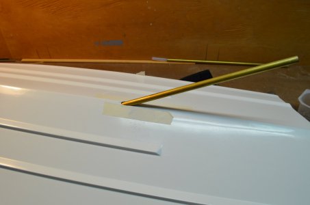
With the prop support mounted on the transom, drilled a hole in the hull where the shaft tube will exit. Then determined the curvature of the tube.
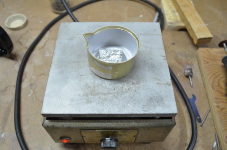
Melted some low temp pot metal in a cat food tin on a hot plate.
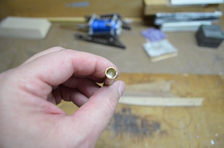
And poured that metal into the brass tube. Let cool.
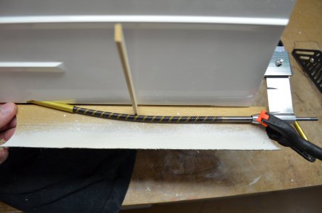
Bent the brass tube over a form to the desired shape. It bends with no dents in the tube and bends to a smooth shape. Reheated the brass tube on the hot plate and let the pot metal run out.
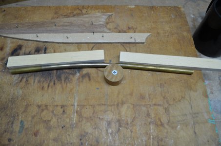
Cut to length and test fit in position.
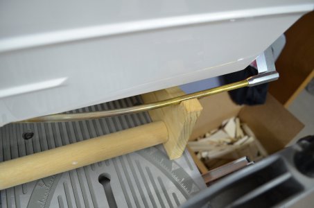
Mounted the brass tube using G-Flex Epoxy. Added some resin white colorant to the mix. Also mounted the motor mounts to the hull.
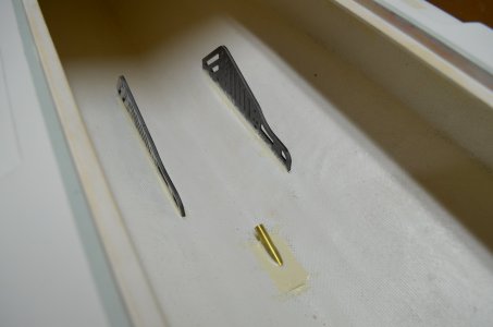
Start making the steering servo foundation. Holes are already drilled in the transom for mounting bolts.
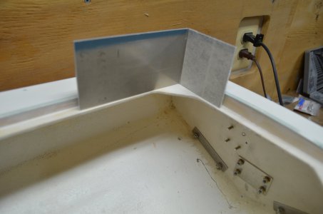
Servo foundation cut the shape.
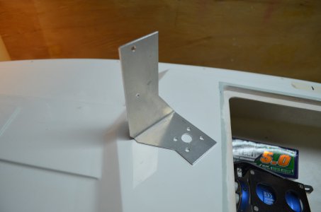
And partially mounted. The metal rod thru the plate connects to the servo and to the rudder. Other backing plates you see are for trim tabs and prop support.
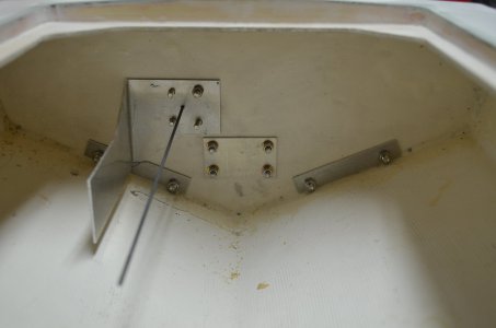
Servo mounted.
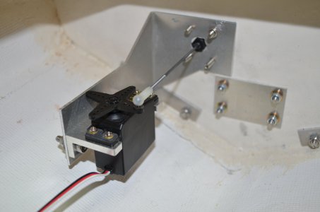
Motor installed on motor mounts. The speed controller will sit above the motor. This will be the biggest motor I will ever use in a model boat.
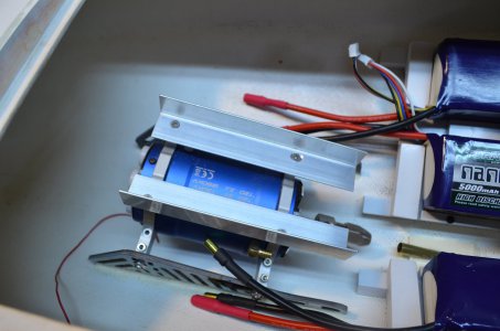
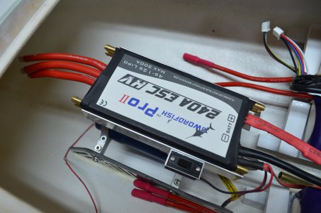
And here we have the speed controller.
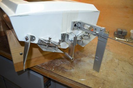
The transom and running hardware. The outer sharp fins are turn fins. The boat runs fine without them. The inner items are trim tabs. When running, if the bow of the boat is too high, the trim tabs are adjusted to bring the bow down for better performance. The prop support can also have the prop angle adjusted slightly.
You can also see the long rudder. Since most fast electric boats run courses clockwise, the rudder is placed on the inside of the turns so the rudder always digs into the water. As the boat makes banked right turns, the rudder with always stay in contact with water. The rudder also has two small holes which are water pickups which send pressured water to cool the motor and speed controller.
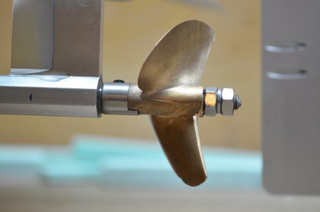
The nasty looking high pitched prop. It's about 2-1/2 inches in diameter.
For the prop shaft, started with a straight section of brass tubing.

With the prop support mounted on the transom, drilled a hole in the hull where the shaft tube will exit. Then determined the curvature of the tube.

Melted some low temp pot metal in a cat food tin on a hot plate.

And poured that metal into the brass tube. Let cool.

Bent the brass tube over a form to the desired shape. It bends with no dents in the tube and bends to a smooth shape. Reheated the brass tube on the hot plate and let the pot metal run out.

Cut to length and test fit in position.

Mounted the brass tube using G-Flex Epoxy. Added some resin white colorant to the mix. Also mounted the motor mounts to the hull.

Start making the steering servo foundation. Holes are already drilled in the transom for mounting bolts.

Servo foundation cut the shape.

And partially mounted. The metal rod thru the plate connects to the servo and to the rudder. Other backing plates you see are for trim tabs and prop support.

Servo mounted.

Motor installed on motor mounts. The speed controller will sit above the motor. This will be the biggest motor I will ever use in a model boat.

And here we have the speed controller.

The transom and running hardware. The outer sharp fins are turn fins. The boat runs fine without them. The inner items are trim tabs. When running, if the bow of the boat is too high, the trim tabs are adjusted to bring the bow down for better performance. The prop support can also have the prop angle adjusted slightly.
You can also see the long rudder. Since most fast electric boats run courses clockwise, the rudder is placed on the inside of the turns so the rudder always digs into the water. As the boat makes banked right turns, the rudder with always stay in contact with water. The rudder also has two small holes which are water pickups which send pressured water to cool the motor and speed controller.

The nasty looking high pitched prop. It's about 2-1/2 inches in diameter.

Last edited:
- Joined
- Feb 13, 2023
- Messages
- 63
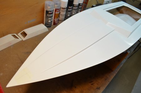
Here's a good picture of the bow where those hatches were removed and patched over.
Here's a view of the motor. You can set it up to run at two different settings. You wire it up by connecting the wires a certain way on end, the left side in the picture. I'm using the 1280kv setting. And using 2 4S Lipos in parallel per motor. So each motor is running on about 30 volts. As of today I'm on my third set of Lipo batteries.
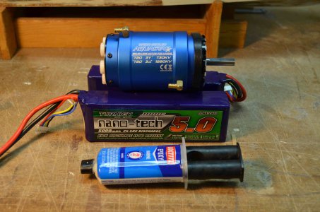

Here's a view of the motor. You can set it up to run at two different settings. You wire it up by connecting the wires a certain way on end, the left side in the picture. I'm using the 1280kv setting. And using 2 4S Lipos in parallel per motor. So each motor is running on about 30 volts. As of today I'm on my third set of Lipo batteries.

- Joined
- Feb 13, 2023
- Messages
- 63
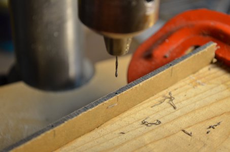
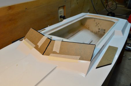
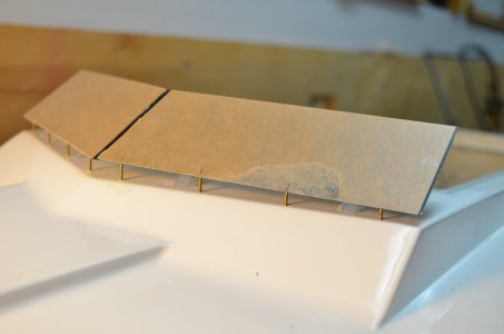
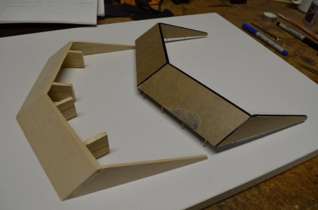
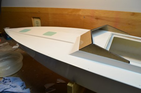
For the windshield I first made a wood template. Then cut each piece from black acrylic. Holes were drilled in the bottom of each piece for brass locator pins. Clear acrylic was fastened on the deck so that when glued together the front section had the same sweep angle to them. Then the side pieces were added.
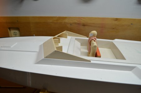
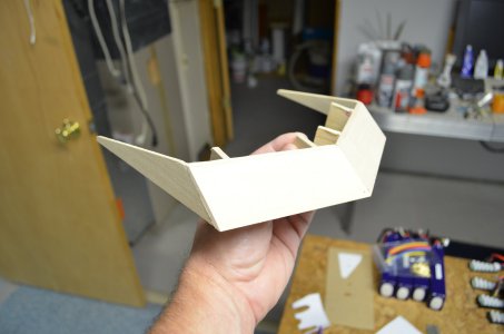
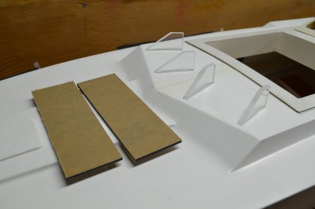


- Joined
- Feb 13, 2023
- Messages
- 63
I needed figures for this boat. Other models like the SS Miss Belmar also needs figures but those figures will be small and I need a variety of people which makes it more difficult. This boat I only need three figures and they all look the same. We had a club member that passed away in 2012. His larger scale models like this one, he always made figures. He was an art teacher and he was good at making figures and encouraged the club to do so, but no one really tried. Anyway....
I looked over the handouts that the art teacher gave us and looked online on how to start. I did not need facial features. Motor cycle riders seemed to foot the bill. Figures with helmets and jump suits, and they would be wearing life jackets. I started with the bodies and the heads, more like helmet-heads. The first round of hemlet-heads I made too small. And they did not look right, the following three pics.
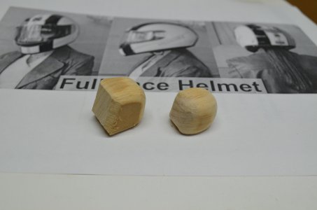
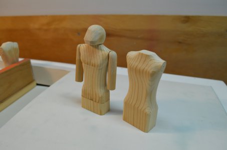
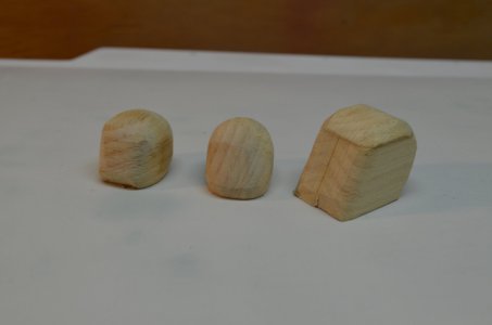
These are the bodies. They only needed to be half bodies as I did not need the legs. For my first time at this they came out pretty good for what I was looking for. These are still in the shaping process with the Dremel drum sander and files. Never did something like this before.
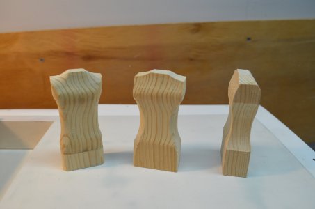
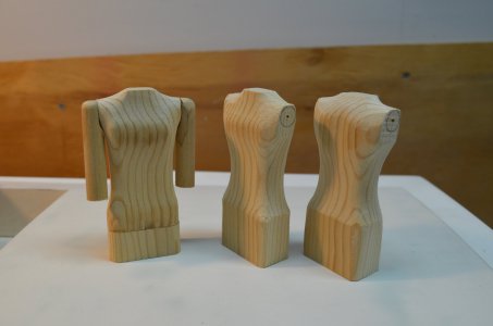
Shaping continues. Holes are drilled for the arms and my first attempt at arms, eventually discarded. Since Betty Cook is a woman, I made the one on the left with a slight raised area in the chest. They are also slightly different heights.
Pretty sure these are the start of the second batch of heads.
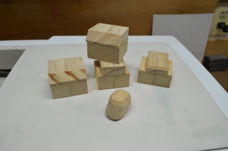
They look like Mandolorian heads, the ones on the left.
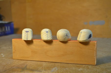
Making progress. The dark marks where ears would be were a guide for shaping so I get the roundness even on each of them.
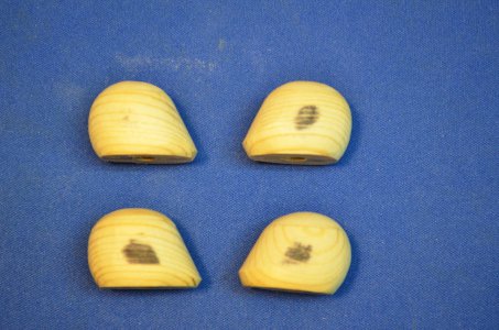
A hole was drilled for the necks and dowels inserted. Once they where done the helmet-heads where not glued onto dowels. That way they could be turned slightly. There is also a styrene template to make sure the helmet-heads all have the same profile and shape.
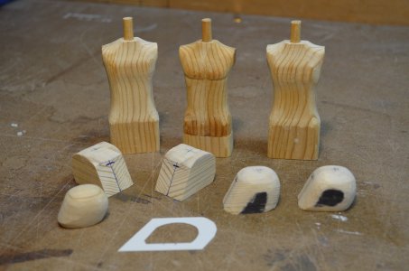
Next up as I go through the pictures I'll describe how I made the moveable arms.
I looked over the handouts that the art teacher gave us and looked online on how to start. I did not need facial features. Motor cycle riders seemed to foot the bill. Figures with helmets and jump suits, and they would be wearing life jackets. I started with the bodies and the heads, more like helmet-heads. The first round of hemlet-heads I made too small. And they did not look right, the following three pics.


These are the bodies. They only needed to be half bodies as I did not need the legs. For my first time at this they came out pretty good for what I was looking for. These are still in the shaping process with the Dremel drum sander and files. Never did something like this before.

Shaping continues. Holes are drilled for the arms and my first attempt at arms, eventually discarded. Since Betty Cook is a woman, I made the one on the left with a slight raised area in the chest. They are also slightly different heights.

Pretty sure these are the start of the second batch of heads.

They look like Mandolorian heads, the ones on the left.

Making progress. The dark marks where ears would be were a guide for shaping so I get the roundness even on each of them.

A hole was drilled for the necks and dowels inserted. Once they where done the helmet-heads where not glued onto dowels. That way they could be turned slightly. There is also a styrene template to make sure the helmet-heads all have the same profile and shape.

Next up as I go through the pictures I'll describe how I made the moveable arms.
- Joined
- Feb 13, 2023
- Messages
- 63
Lots of pictures for the arms.
Just noticed the male chest detail on the center figure, lol.
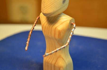
The armature for the arms is 12 gauge Romex electrical wire with insulation removed. To help hold the clay from moving I soldered smaller gauge wire onto the Romex as an anchor.
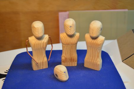
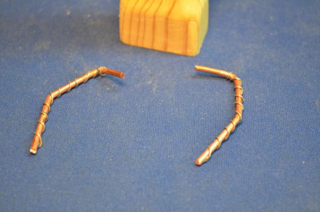
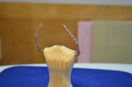
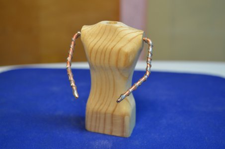
The arms are inserted into previously drilled holes. The arms will not be glued into the body, that way the arms can be moved up and down.
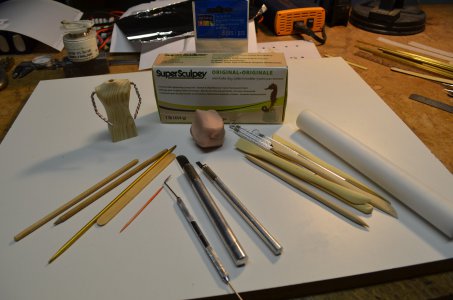
I'm using this clay called SuperSculpey that I bought at Michaels craft store. Once you have the desired shape of your subject, you place it in the oven for the specified time & temp on the package and it comes out hard. Here are some of the tools I'll be using for shaping the arms.
Arms rotated up.
And down.
Clay was rolled flat.
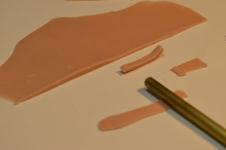
And applied in layers.
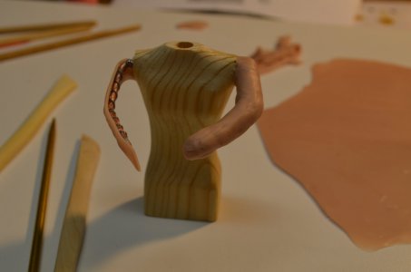
Eventually got the shape needed. Using the tools I reduced the diameter and shaped the shoulders and elbows. The shoulders had to be shaped so that when the arms were rotated up, they still joined into the body smoothly. The hand ends were eventually trimmed and a hole created. Someday, still haven't, will have to make those gloved hands. Isn't the rule build something to the 98% point then you are 'done' for now? LOL
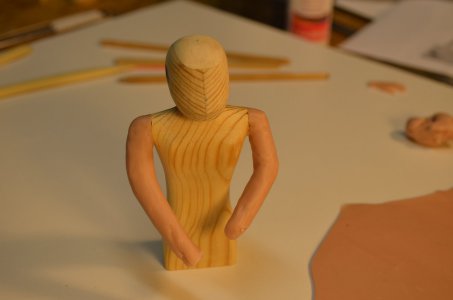
Starting to use toothpicks and other pointy narrow tools to make creases in the jumpsuit arms.
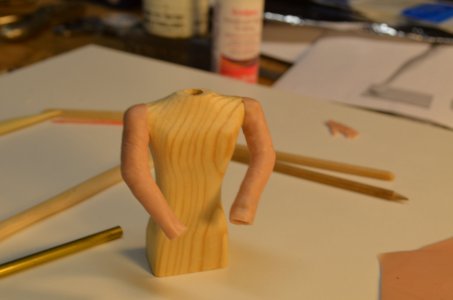
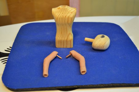
And it all comes apart.
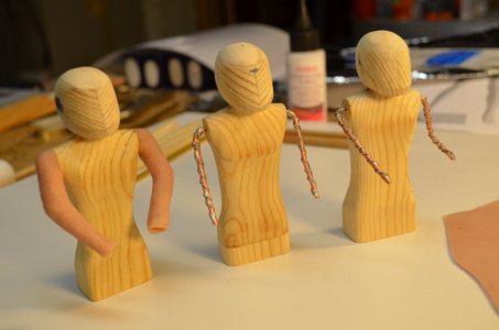
Progress. Each figure the arms are a different shape. The one on the left (Betty) has her arms positioned for driving the boat and holding the steering wheel.
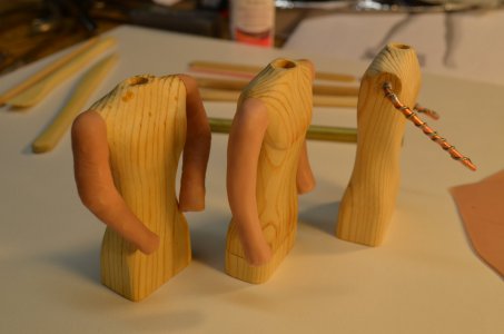
You can see the creases. Had to references online pictures to get the crease direction and depth correct.
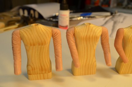
The left one the shoulders are too pointy.
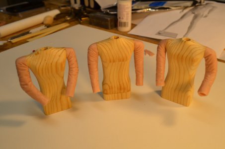
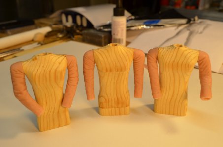
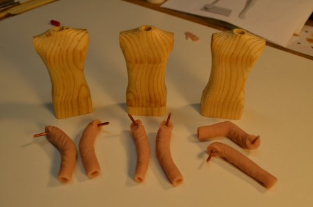
At this point the helmet-heads and bodies have been sealed I think with resin and the arms were fired in the oven. Face masks are cut from styrene. Four helmet-heads were made, take the best three of the group.
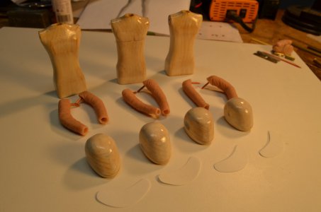
Next up are the life jackets.
Am I showing too much detail?
Just noticed the male chest detail on the center figure, lol.
The armature for the arms is 12 gauge Romex electrical wire with insulation removed. To help hold the clay from moving I soldered smaller gauge wire onto the Romex as an anchor.


The arms are inserted into previously drilled holes. The arms will not be glued into the body, that way the arms can be moved up and down.

I'm using this clay called SuperSculpey that I bought at Michaels craft store. Once you have the desired shape of your subject, you place it in the oven for the specified time & temp on the package and it comes out hard. Here are some of the tools I'll be using for shaping the arms.

Arms rotated up.

And down.

Clay was rolled flat.

And applied in layers.

Eventually got the shape needed. Using the tools I reduced the diameter and shaped the shoulders and elbows. The shoulders had to be shaped so that when the arms were rotated up, they still joined into the body smoothly. The hand ends were eventually trimmed and a hole created. Someday, still haven't, will have to make those gloved hands. Isn't the rule build something to the 98% point then you are 'done' for now? LOL

Starting to use toothpicks and other pointy narrow tools to make creases in the jumpsuit arms.

And it all comes apart.

Progress. Each figure the arms are a different shape. The one on the left (Betty) has her arms positioned for driving the boat and holding the steering wheel.


You can see the creases. Had to references online pictures to get the crease direction and depth correct.

The left one the shoulders are too pointy.


At this point the helmet-heads and bodies have been sealed I think with resin and the arms were fired in the oven. Face masks are cut from styrene. Four helmet-heads were made, take the best three of the group.

Next up are the life jackets.
Am I showing too much detail?
- Joined
- Feb 13, 2023
- Messages
- 63
The life jackets.
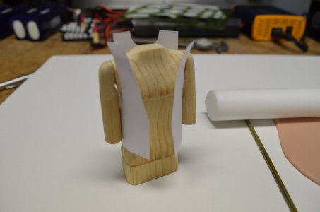
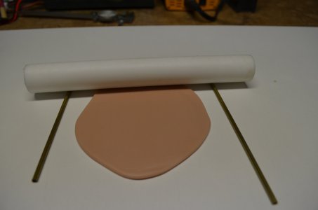
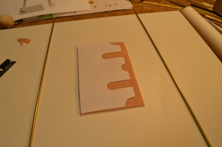
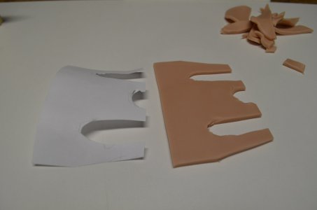
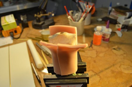
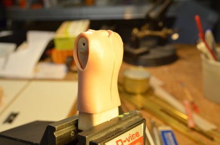
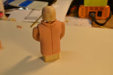
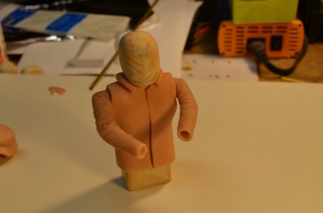
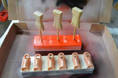
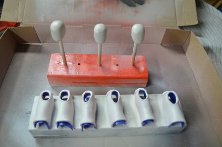
Started out with a paper template. Rolled and kneaded the clay to soften it then rolled it out on a melamine surface. Used two pieces of brass to roll the roller on to get a uniform thickness. Applied the template and cut with an Exacto. Applied to the body and continued to shape it. Each life jacket had to be in two pieces so I could slip the halves on the body. Applied a collar ring. Then heated in the oven. Sealed the clay, primed, then spray with international orange.
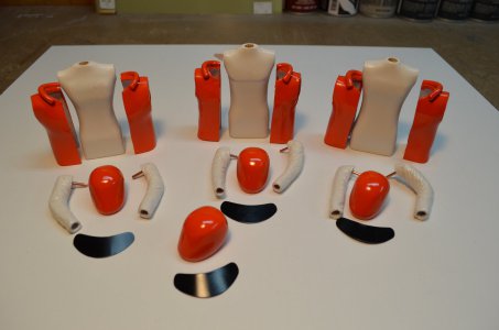
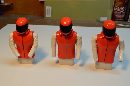
Still have to make gloved hands, someday I will. Notice the arms pivot at the shoulder, right figure. And the heads pivot, center figure. And the driver can hold the steering wheel. There is still a lot of detail I can add to the life jackets, lettering, straps and buckles etc. Again, someday I will. Also notice the windshield.
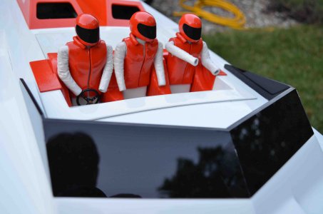
Started out with a paper template. Rolled and kneaded the clay to soften it then rolled it out on a melamine surface. Used two pieces of brass to roll the roller on to get a uniform thickness. Applied the template and cut with an Exacto. Applied to the body and continued to shape it. Each life jacket had to be in two pieces so I could slip the halves on the body. Applied a collar ring. Then heated in the oven. Sealed the clay, primed, then spray with international orange.


Still have to make gloved hands, someday I will. Notice the arms pivot at the shoulder, right figure. And the heads pivot, center figure. And the driver can hold the steering wheel. There is still a lot of detail I can add to the life jackets, lettering, straps and buckles etc. Again, someday I will. Also notice the windshield.

