Showing off my RC model boats

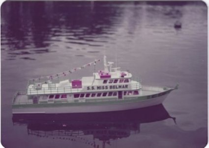
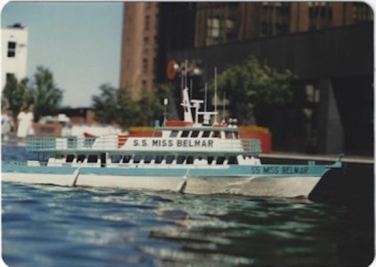
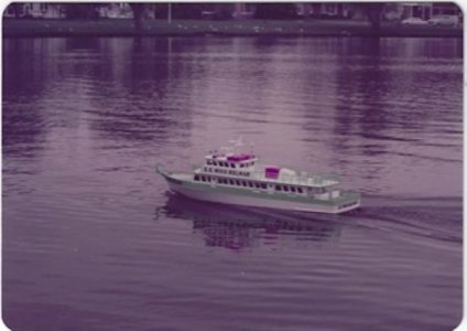
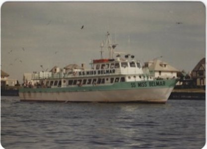
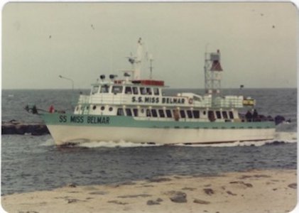
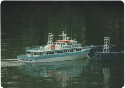
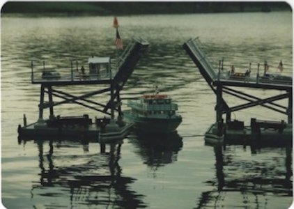
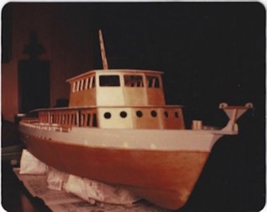
These pics are when I first built the model in the 70's. I had to scan them from prints so the quality is poor.

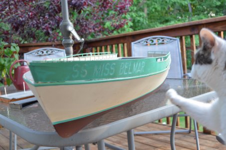
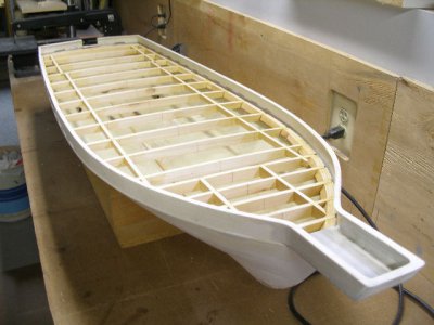
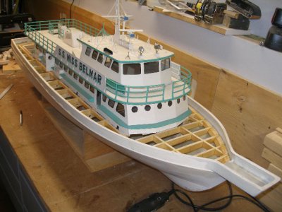
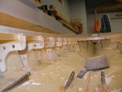
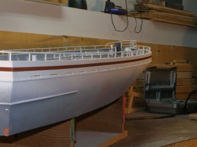
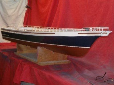
This was built as plank on frame. The frame of the boat was model quality plywood. The skin of the hull was glued on the frame then fiberglassed with polyester resin and cloth.

ZJ MBM 1.jpg

This picture was prior to selling the original hull.

ZB DSC_0071.JPG

Running the model at the lake....

ZK MBM 2.jpg

ZL MBM 3.jpg

ZM MBM 4.jpg

The real boat in Shark River.

ZMiss Belmar 1 SR.jpg

Entering Shark River Inlet.

ZMiss Belmar 2 SR Inlet.jpg

At our club events someone made a pair of jetty's that we had to navigate through. Much like the above picture.

ZMiss Belmar 6.jpg

We also had a working bridge that would have been like the bridge entering Shark River. You had to blow your boats horn for the bridge to open. There were wires that went underwater to a control box.

ZMiss Belmar 7.jpg
 
Yup four screws.

These are build pictures for the rebuild of the boat using a fiberglass hull from the mold.

E P4060171.JPG

Test fitting the old original cabin and pilot house on the new hull.

F P4240195.JPG

A bit of the inside framing.

G P4240212.JPG

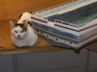
Painting in progress.

H P1310708.JPGI P1150677.JPGJ P2150741.JPG

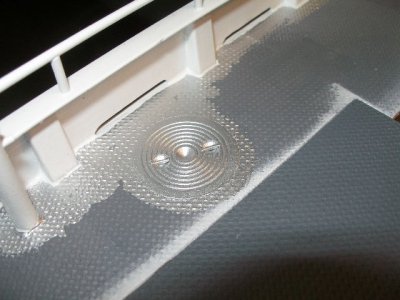
The deck of the model has realistic diamond plate. The diamond plate consists of metal window screen impregnated with polyester resin. A layer of resin is applied to the deck, the screen is put down on top of the wet resin and allowed to set. Then additional coats of resin are applied.
Here the deck has been primed with gray. Then a coating of silver paint is applied. The top coat is a coating of Humbrol Steel color paint.
The acrylic round deck plate was made on a friends lathe. I now have my own lathe.

K P2270755.JPG
 
Found the picture of the inside of the hull. No longer using the NiMH batteries. Too many cells died. Using a sealed lead acid battery now. I get about an hour running time. Here are pictures of the real boat being built... ...

View attachment 464760View attachment 464763
Ken:

Thanks for your posts and pictures. I am really impressed.

Do any of you guys run your models on IC engines? If so have you considered building one for your Miss Belmar? Just curious. You have piqued my interest in yet another time-hog hobby.

Also, when you mentioned that Miss Belmar was built in Louisiana and I saw your photo, It immediately looked to me like Delcambre, which is close to Franklin on the Atchafalaya. And Franklin is where Gulf Craft, LLC is located! Did you get to watch as the original boat was being built - and spend time in that part of the country? My mother's side of the family happens to be from Youngsville, just west of Franklin.

Thanks again for the interesting post.

Bill
 
Thanks Bill.
If we had gas engines we would not be able run on any lakes around here. Much too noisy. Electric motors models you can run just about anywhere. IC engines, the rpm output would be way too high anyway. The Dumas motors in the Belmar output maybe 5000 rpm and they are further geared down.

Never been to Louisiana and don't know where anyplace is there. Although there is supposed to be a big WWII Museum there I would love to go to. And a restored PT boat.

Time-hog hobby? Very much so. I'm retired and just about spend 5 days a week from 10-6 in my shop.

I have a few other boats to post. And one more on the Miss Belmar.
 
Last edited:
Last post hopefully on the Miss Belmar. Here are some detail pictures with explanations.

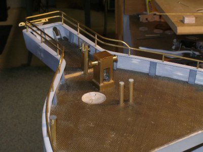
Here you can see the unpainted diamond plate deck and deck plate. Also the brass railings and the anchor windlass. The brass is from K&S metals. The railings are 3/32 brass tubing. Each junction has a 1/16 brass pin to help solidify the joint when it gets soldered. The anchor windlass, the squarish thing in the middle, is a bunch of sheet brass also soldered. That was difficult to solder with the many facets. The round rollers on each side were made on a lathe and they do spin. The two posts nearer the front of the picture are tubes that the anchor line would go down to the rope locker. I planned on making a winch so the anchor would drop sand raise but never did. It would be for display only as dropping an anchor in could foul in weeds which would be hard to clear.
L PB300456.JPG

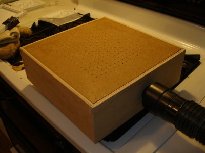
In order to make the floodlights on the upper deck I had to come up a way to make them. This device is a vacuum forming fixture. The vacuum is connected on the right. Styrene is heated in the over then dropped on the perforated platform and sucked into shape.
M P9120149.JPG

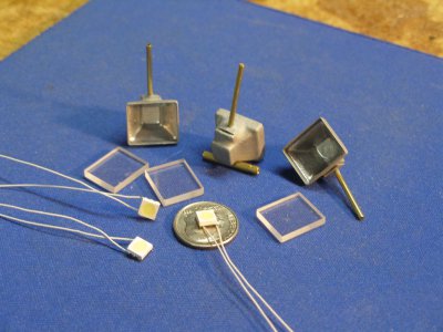
These are the lights made with the vacuum form above. Had to cut & file acrylic for a lens. Solder surface mount wires to the LED's. And a brass post to the styrene as a mount point. You can see the LED's in previous pictures I posted.
N PA120211.JPG

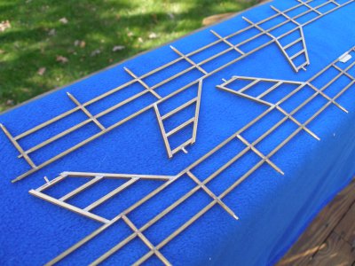
These are the unpainted brass railings on the upper deck. Again each joint is pinned and soldered.
O PB140268.JPG

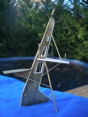
This is the mast on top of the pilot house. It was cut by a friend on his Bridgeport CNC machine. He recently passed away, sad. He was master machinist by trade and had his own business until he retired.
P PB120212.JPG

Float test in the pool. The hull is just about done at this point. The cabin/pilot house still has not been updated and is in the old colors.
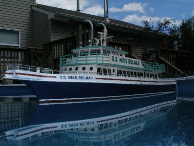
Z P5160091.JPG
 
Back
Top