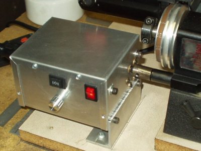
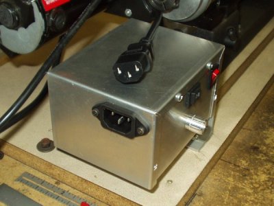
Okay, the 200 rpm motor arrived the other day and everything is back together again. I made a few unscientific tests and I'm satisfied with the results I got.
Now, I know this isn't going to be for everyone, but it works for me. I tend to take fairly light cuts when turning. Usually .01 per side, but sometimes .02 depending on the material. I have seen mention here and on other sites of cuts around .05 deep. That's just not my style. I may baby this lathe, but again, that's just me. If you decide to do something similar, all the components I used were found on line with very little searching. There are plenty of choices to make, and with some careful shopping, this can all be done for less than $50.
Be sure the lathe is properly adjusted, cleaned and lubricated. I noticed a change in the pitch of the motor as the saddle moved along the length of the bed. I found some light corrosion and dust on the bed ways from sitting unused and uncovered for about a month. Also, be sure your tooling is sharp, secure and set up properly.
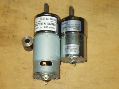
So, here we go. This first picture shows the difference between the two motors. The large one weighs around twice as much as the smaller one, and a lot of that is due to a larger armature. It was advertised as "high torque" and compared to the smaller one, this is true. One simple test I did was to try to stop the motion of the saddle with my finger. Barely slowed it down. Making a .01 deep cut in steel didn't strain the drive much at all. Now it's just going to be a process of finding settings on the speed dial for things I need the drive to do.
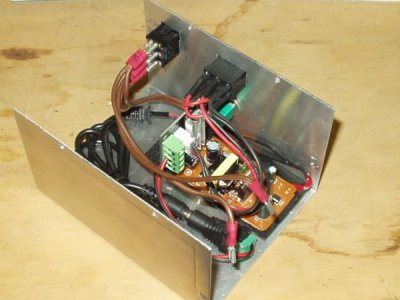
This next picture shows the various electrical components in the enclosure. It took some time through trial and error to come up with something that worked, and this can still be improved upon. I plan to clean up the coil of black wire, as it takes up too much valuable space in the little 3x4x5" box. The circuit board on the bottom of the box is the power adapter. It was removed from the shell it came in and hot glued to a piece of plastic that was hot glued to the bottom of the box. Mounted vertically at the left end of the power supply, is the speed control. It came with a pre-wired switch to handle direction changes for the motor. I know it looks kind of cluttered in there, but sometimes you just need to think differently. This is what I needed to do to get everything to fit. The small blue block you see near the bottom center of the picture is a terminal block that made hooking up the 12VDC output from the power adapter very simple.
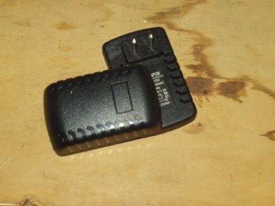
Here is the shell of the power adapter. I cut it along the parting line with a hobby saw, and when the two halves came apart, I cut the two main power leads from the back side of the prongs that plug into the wall. I was amazed at how little was actually inside that shell. I performed the surgery on the shell when it couldn't be make to fit in the space available in the box.
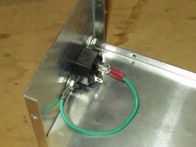
The last thing I want to show is how to ground the main power coming into the metal box. The power entry port I used made this very easy, as it has blade type connectors on the back. All three lugs are marked as to how they should be hooked up. Line, neutral and ground. The circuit board from the power adapter was also marked for polarity, as are the connections on the speed control. As long as you watch for polarity markings on the different components, it should all go pretty smoothly. The first motor I tried ran in the directions called for when the switch was set for left or right. The larger motor has a mark that I took to be for the positive lead, but it ran backward compared to the first one. Test these things before final assembly to save time and effort. Mark things up so you know where leads go if it is taken apart, and there should be few problems. At least I didn't have any smoke come out of mine.
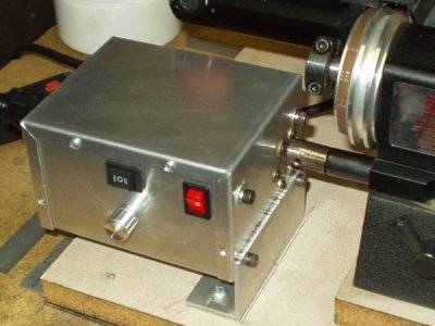
And finally, here is the same picture from a previous posting showing the completed control in place.
Okay, I think I've covered everything. Now I need to find excuses to make some chips.
Russ

