V. Miscellaneous
C. Taper attachment
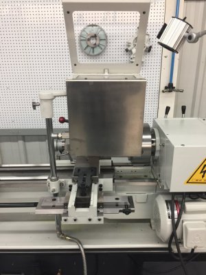
Like most things we purchase for our shop I had a project in mind when I purchased it. The part that I wanted to make was to be made of titanium, was about 4” long, about 3/8” in diameter and had about a 1 degree taper. My order of operations did not include turning between centers and I didn’t particularly want to offset my tailstock since I wasn’t keen about readjusting the lathe every time I wanted to create a taper. I did a bit of reading and discovered that there are four ways, that I could find, to create a taper on a manual lathe. The title of this sections tells you the end of the story but let me tell you how I got there.
The four ways to create a taper on a manual lathe
1. Using the compound
2. Offsetting the tailstock
3. Tailstock offsetting device
4. Taper attachment
1. Using the compound is simple, just rotate the compound to half the angle required and cut:
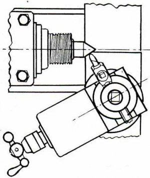
This unfortunately would not work for me since it is only good for short lengths and relatively acute angles.
2. Offsetting the tailstock is much better than using the compound for longer pieces and small angles like I need but I was not planning on turning between centers and this technique requires re-adjusting the lathe every time you use this technique. So, this would not work for my purpose.
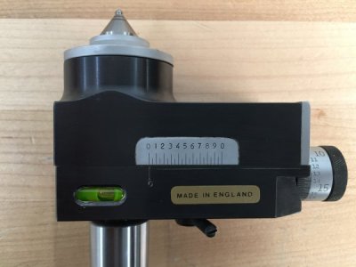
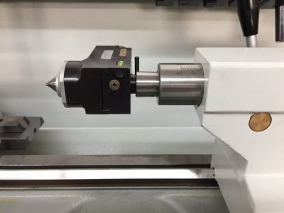
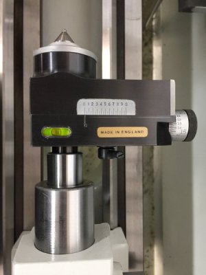
3. Tailstock offsetting device. This was getting closer; it offsets the tailstock but does not require re-setting the ailstock when you are finished. I knew I was not going to use this technique but during my research I found a beautifully made offsetting device made by Royal and purchased it. The device has a micrometer for setting the offset, a ball-nosed live center and a spirit level for making sure the device is level:
.
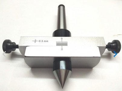
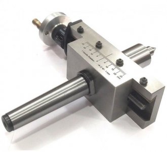
This one, unfortunately, is no longer manufactured but there are some others available new on eBay:
.
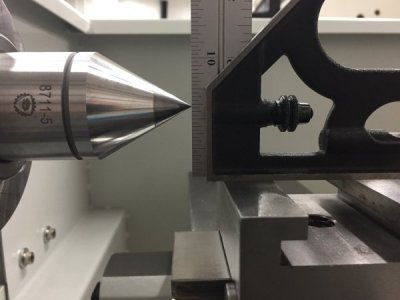
Why the spirit level on the Royal unit? Well, in every source that I read about turning a taper they all mention the importance of starting, and keeping, the cutting tool at the level of the axis of rotation or one will get inconsistent results.
Using the table that came with the tailstock offset device and Dr Jackson’s formula for calculating the error in cutting depth created by a vertical error(in this case the rotation away from level of the tailstock offset device). Let me walk through how significant this is. If you have an aversion to math just skip this and go to the next section. Here is part of the table that came with the Royal device:
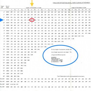
If you look at the blue oval it gives directions and an example for using the chart. So, for a 2 degree taper on a 5” workpiece one offsets the device .087”. This is the reduction in the radius of the workpiece. Easy enough, but what if the offset device is not level and it raises or lowers the workpiece, say 0.1” on a 0.25” radius workpiece. Using Dr Jackson’s formula the change in depth of cut would be 0.02”((.1x.1)/(2x0.25)). So, at the end of the cut nearest the offset device you would not see the radius reduced by 0.087”, like you expected, but instead it would be reduced by only 0.067”. That is a 23% reduction in your taper at the end of the workpiece. What is even worse is that the elevation or depression of the workpiece will change as you go from the spindle, where there is minimal displacement, to the offset device, where it is maximal. Unfortunately, the Royal offset device does not work for my application because I am not planning on working between centers for this project but it is a work of art and I now know I must be very careful to make sure it is level, and stays level, when I use it.
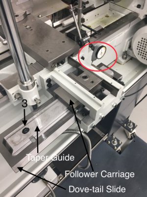
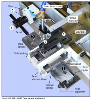
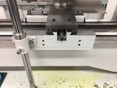
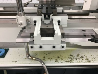
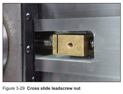
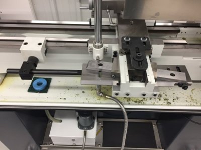
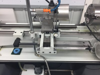
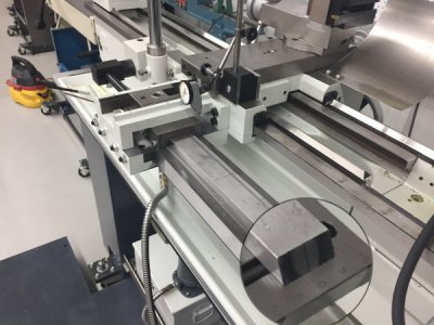
4. Taper attachment- this turns out to be the tool that I need for my project. It can create a taper of +/-10 degrees over a length of ten inches, I don’t have to change my order of operations to include turning between centers and I don’t have to re-calibrate the lathe once I am finished. The only disadvantage is that the cross slide lead screw needs to be disconnected and the drawplate needs to be reconnected when the taper attachment is in use. The instructions in the PM Manual are very good so I will just show you a few photos from the Manual and of my installation on the 1236-T with the splash guard removed. Basically you bolt it onto the four pre-drilled holes on the backside of the carriage and zero it.
Attaching to the carriage:
.
Removing the bolt to the cross slide leadscrew nut:
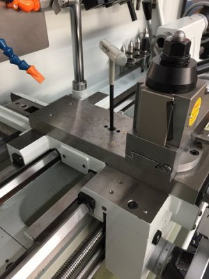
.
Clamp and tie rod as well as draw plate are attached:
Zeroing:
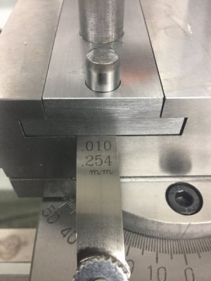
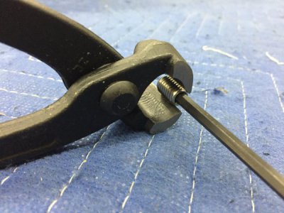
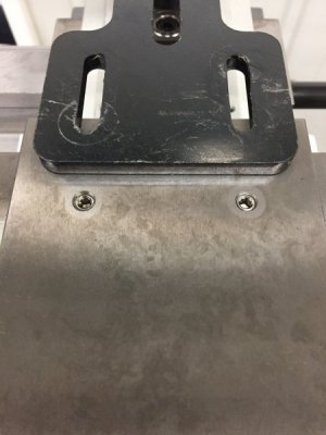
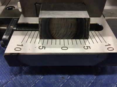
The attachment comes without a reference mark on the taper guide. This is added once the taper attachment is zeroed:
That’s it for the PM taper attachment.

