-
Welcome back Guest! Did you know you can mentor other members here at H-M? If not, please check out our Relaunch of Hobby Machinist Mentoring Program!
You are using an out of date browser. It may not display this or other websites correctly.
You should upgrade or use an alternative browser.
You should upgrade or use an alternative browser.
Servo running rough
- Thread starter matthewsx
- Start date
- Joined
- Jan 29, 2017
- Messages
- 311
So how did you go?
I've just bought one of these to drive my dbit grinder and want to know if you retained the pedal controller or changed it out for another method.
My pedal controller has a magnet and what looks like a hall effect sensor.
I think these motors have a great future in driving smaller power tools.
I've just bought one of these to drive my dbit grinder and want to know if you retained the pedal controller or changed it out for another method.
My pedal controller has a magnet and what looks like a hall effect sensor.
I think these motors have a great future in driving smaller power tools.
- Joined
- Jan 2, 2019
- Messages
- 7,154
Embarrassed to say I haven't made much progress since the last post. I did get my "new" lathe up and running and will modify or make new pulleys as I don't think the stepped ones are appropriate for this application.
I do think the price point on these things makes them very appealing and will let folks know when I dig back into the control for it.
John
I do think the price point on these things makes them very appealing and will let folks know when I dig back into the control for it.
John
- Joined
- Mar 25, 2013
- Messages
- 5,131
Those round tuits work very well. I made a modification to the control circuit so that I can turn it on without turning the speed to zero and also get a greater range of speed control. I can share it if you want? If you bought it from that guy on eBay, it may already have my modification since I gave him the schematic?
- Joined
- Jan 2, 2019
- Messages
- 7,154
I’d love a copy of your schematic. Sure I could figure it out but be better not to wait another yearThose round tuits work very well. I made a modification to the control circuit so that I can turn it on without turning the speed to zero and also get a greater range of speed control. I can share it if you want? If you bought it from that guy on eBay, it may already have my modification since I gave him the schematic?
- Joined
- Jan 29, 2017
- Messages
- 311
Do tell Robert
- Joined
- Mar 25, 2013
- Messages
- 5,131
Took me a while to find it!
First you might find the attached manual helpful if you don't have it. It allow you to change the start and stop speeds and other parameters. Also shows the error codes.
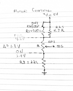
Here is my schematic:

This replaces the foot pedal speed control that I assume your motor came with? If not, it plugs into the back of the controller. The pin inputs are also shown on the attached manual.
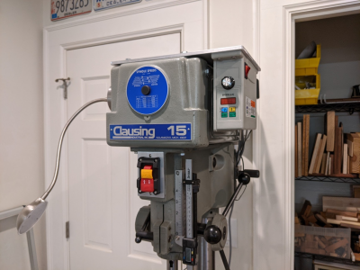
My circuit is basically just a voltage divider circuit but the resistances were carefully selected by trial and error. The power switch on the controller is still used as a master power switch. That switch also turns on my work light. The run/stop switch is added. For my application I used the factory switch on my drill press. The speed control is a 1K potentiometer with the signal to the controller coming off the center tap. I mounted this in the controller box for convenience.
You may note that the motor starts when the input voltage is around 2.4volts and hits max at 4.2 volts (delta voltage 1.8v.) The response is non-linear so I had to buy a reverse audio taper pot for optimum performance. I am assuming all of these controllers are very similar if not identical. I would mock it up on a breadboard first and make sure it works for your controller.

First you might find the attached manual helpful if you don't have it. It allow you to change the start and stop speeds and other parameters. Also shows the error codes.
Here is my schematic:

This replaces the foot pedal speed control that I assume your motor came with? If not, it plugs into the back of the controller. The pin inputs are also shown on the attached manual.
My circuit is basically just a voltage divider circuit but the resistances were carefully selected by trial and error. The power switch on the controller is still used as a master power switch. That switch also turns on my work light. The run/stop switch is added. For my application I used the factory switch on my drill press. The speed control is a 1K potentiometer with the signal to the controller coming off the center tap. I mounted this in the controller box for convenience.
You may note that the motor starts when the input voltage is around 2.4volts and hits max at 4.2 volts (delta voltage 1.8v.) The response is non-linear so I had to buy a reverse audio taper pot for optimum performance. I am assuming all of these controllers are very similar if not identical. I would mock it up on a breadboard first and make sure it works for your controller.

Attachments
Last edited:
- Joined
- Jan 2, 2019
- Messages
- 7,154
Do tell Robert
Awesome, just what I needed to move forward....Took me a while to find it!
First you might find the attached manual helpful if you don't have it. It allow you to change the start and stop speeds and other parameters. Also shows the error codes.
Here is my schematic:
View attachment 407872
This replaces the foot pedal speed control that I assume your motor came with? If not, it plugs into the back of the controller. The pin inputs are also shown on the attached manual.
My circuit is basically just a voltage divider circuit but the resistances were carefully selected by trial and error. The power switch on the controller is still used as a master power switch. That switch also turns on my work light. The run/stop switch is added. For my application I used the factory switch on my drill press. The speed control is a 1K potentiometer with the signal to the controller coming off the center tap. I mounted this in the controller box for convenience.
You may note that the motor starts when the input voltage is around 2.4volts and hits max at 4.2 volts (delta voltage 1.8v.) The response is non-linear so I had to buy a reverse audio taper pot for optimum performance. I am assuming all of these controllers are very similar if not identical. I would mock it up on a breadboard first and make sure it works for your controller.
View attachment 407873
And encouraging to see that it works for your application, should be fine for mine too.
Thanks,
John
- Joined
- Jan 29, 2017
- Messages
- 311
Brilliant, should have learnt electronics when younger.
Revision number is exactly the same as mine.
I will get all the components as used by yourself and build and test.
Can't possibly go wrong if we share the same software.
Thank you for your efforts and willingness to share them.
Robert, you should save this data in the downloads section for others willing to use these small motors for their projects.
Best regards

