RF-30 Clone Power Head Lift, VFD, More Mods and Fixes

Hi, I appreciate your interest. If you reread the description carefully I described how there is a cross pin that keys the gear to the shaft. It is a slip fit through a hole in the new shaft you will make and the slot in the gear is closed-ended to retain the pin once everything is assembled. Note what I said about the shaft needing to be able to slide further into the gear housing to install the pin as you are assembling the gearbox. I'm talking about the change from the shaft size for the housing and gear and where I expanded it into a socket to go over the shaft on the mill where the crank was. Please let me know if I can make this more clear for you. I just did some searching myself for the actuator motor and I couldn't spot one for a better price than you have found.

I lubricated the lift gears in the head by spraying a bunch of WD-40 Gel Lubricant up there, handy stuff.

Rob
 
Ah - thanks. Yes, you did have that info in there - I guess I just did not read it carefully enough. My little lathe may take days to make a combined shaft and coupler - I may just make a shaft from smaller diameter stock and then a coupler that uses grub screws against flats on both ends just like the crank handle does now.

Much appreciated!

Tom
 
Very nice work and clever ideas. I did all this stuff to my RC mill/drill as well. It always amazes me how many ways there are to get the job done!
 
I ordered the motor and decided to spend a little more and get a new one. I also contacted the manufacturer and they have no drawings showing the construction of the assembly which I thought was odd. I do see some Chinese knockoffs of this style incline motor out there so I am sure they have them but they just don't give them out.
 
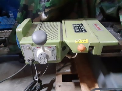
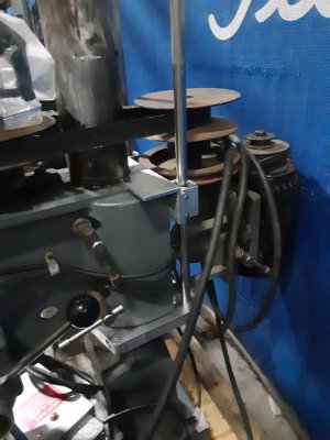
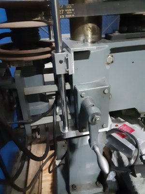
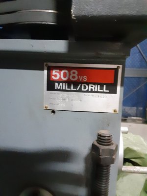
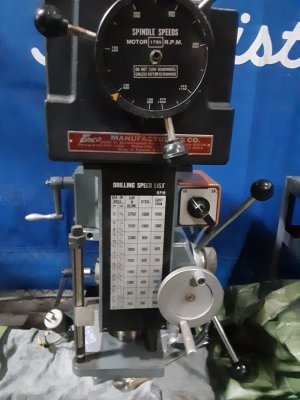
I finally have a few pics of the one I bought, but it's still sitting on a pallet till I get my act together at home....I added my version of keeping the head in line as you move it, Thompson linear rods and bearings mounted to a 7075 alum. collar. Haven't actually proven it holds zero, but I'm sure it will help:<) I got it with the voltage converter, 6" vice on a swivel base, collets and a massive steel table which I have added wheels and stops too already. Didn't get a pic of that yet. $500 ;)
 

Attachments

  • 20220317_075138.jpg
    20220317_075138.jpg
    458.5 KB · Views: 26
  • 20220420_050159.jpg
    20220420_050159.jpg
    235.2 KB · Views: 29
  • 20220420_050214.jpg
    20220420_050214.jpg
    236.5 KB · Views: 24
  • 20220420_050312.jpg
    20220420_050312.jpg
    209.4 KB · Views: 25
  • 20220420_050327.jpg
    20220420_050327.jpg
    233.4 KB · Views: 26
Nice! A "hold the X" mod is on my list once I get through the power lift. One thing that has always puzzled me is that every design I have seen uses a clamp around the column as a fixed point. Why not drill and tap some holes in the base and use that to mount the vertical ground rods? At first I thought it might be because the column may rotate a bit relative to the base, but if that were the case the X would be lost relative to the table which is connected to the base. It seems a heck of a lot easier to build something that attaches to the base than a big round clamp on the column.
 
Question……
How does the new output shaft mate to the original hand crank shaft?
 
A coupler with grub screws on the flats just like the handle uses. @Gravydog got fancy and (apparently) turned some steel stock large enough to bore a socket to fit over the shaft on the mill and turned a shaft down to fit in the gear reducer. I am not going to get that fancy (I have a tiny lathe) so I am just going to turn a coupler that uses grub screws on both ends.
 
Back
Top