Replacing G0709 spindle bearings

Yes, I clearly need to check more thoroughly for grit in the other bearings. I won't rule out replacing any or all of the other bearings. And I need to make sure I can get this well cleaned.

I just checked, and I don't see any cracking on the rollers. I think it's a trick of light in the picture. Nevertheless, the wear is obvious on the rollers as well as the race. Once I get that ring off the spindle nose, I'll be able to take more pictures.
 
Sounds like your experiences are about the same as mine. Although I was able to get the c clip off but knew I would not be able to get it on in a smooth manner. So I to purchased large locking c clip pliers off Amazon for 42 bucks. Nice thing is every once in awhile I come across these monster snap rings so they will get used.
I see your spindle side bearing is a p5 rating. Also curious what the black markings on the outboard bearing race. The two black lines going the circumference of the race.
My gear box gears also had overspray on some of the gears. Funny but NOT. Like you found I also had grit on the backside of the races in that channel. Theirs no good way to flush that area when the machine is back together. Is it debris from the bearings setting or is it gearbox debris getting drowned there from the oil holes that feed the bearings. That’s why the small magnets surrounding those holes is recommended.
What’s gonna be your procedure for install? setting the preload? looking good keep us updated.
 
We probably got the same ratcheting c clip wrench set, even if it has a different brand name on it... Mine was HILTEX. I'll probably replace those terrible philips screws with hex heads at some point, at least if I use this much more.

I didn't notice the black interior circumferential circles on the outboard outer race when I was disassembling it. I'm guessing that google decided to "enhance" the picture and make it look more clearly focused, but in any case, that's where the ends of the rollers were running. I looked again at the cleaned bearing and there's some wear in the areas of those lines (though more distributed than you would guess from the picture) so I think that might have been the edges of the rollers grinding up grit! In case I had any doubts about whether I should be replacing them...

Tonight I removed the cage and inner race from the spindle. I removed the keys from the spindle, then I heated the race with a heat gun until the residual oil on it got hot enough to smell. Then I turned the spindle nose-up on some pieces of wood and gently tapped the race with the loose nose bearing retainer. I re-heated the race once or twice, and it took probably a couple of minutes of light tapping before the race neatly dropped onto the supporting pieces of wood (while I kept my grip on the bearing retainer to not drop it as well). To be clear, I wasn't hammering on the bearing retainer; I held it with my fingers on opposite sides, and used it as a very very gentle captive slap hammer, moving it around the bearing as I went to make sure it was getting even pressure so it wouldn't rack.

Yeah, the spindle side bearing is marked P5, and it's definitely etched not stamped. But I don't see an eccentric mark. Here it is with the oil wiped off:
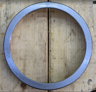
1653004519706.png

Is the "1404 312" is a serial number? It matches the other half, but I don't have anything to compare it to. Sorry, was having trouble with macro focus but it's almost legible here:
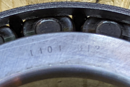
1653004691414.png

Given the lack of eccentric marks (that I can see), does it seem legit that these are P5?

All the ball bearings are turning freely, and they spin freely when I let them go. No bad noises. I think that ball bearings are far more able to reject chips around the side than roller bearings, so that's not a huge surprise. For better or worse, not going to invest on replacing them all right now. I could easily imagine making another decision if I were putting in better bearings.

While I already have some magnets, I'm going to buy more, and clean out the sump with WD40 before I put anything back in.

Re-install after cleaning, something like this: (See comment #35 for what I actually did)
  1. Cut new gaskets (I think; I bought new gasket material, but on the other hand it's not torn)
  2. Lightly oil spindle shaft, heat new chuck-end spindle bearing, install on spindle shaft. Replace clip ring.
  3. Re-install keys in spindle shaft
  4. Lightly oil outer raceways, chill them in freezer
  5. Heat-soak new outboard spindle bearing; set aside
  6. Lightly oil outer raceways; tap with wood to install front and back flush with case
  7. With wood on ways for support, re-install spindle, putting gears back on as it goes through the headstock case. Remember to include the speed shift block properly indexed, or I'll be very sad and have to start over later! Make sure all the clip rings are in place.
  8. Screw spindle side bearing retainer ring in place, seating the spindle bearing race to its intended depth.
  9. Re-heat new outboard spindle bearing, install on spindle shaft.
  10. Screw outboard bearing retainer ring in place, seating outboard outer bearing race to depth.
  11. Install the collar / spacer (also maybe it's a labyrinth seal?)
  12. Use the inner spanner nut to tighten just enough to remove play, not the additional torque for setting normal preload.
  13. Lock inner spanner nut with outer spanner nut
  14. Run clean oil through the taper bearing holes until it flows through
  15. Refill the sump with clean oil, close the top.
  16. Run the full preload procedure, regularly checking temperature with an IR thermometer to make sure bearings aren't overheating, and listening carefully.
  17. Re-install spider

The manual has a preload procedure. In the version of the manual for my lathe ("Mfg. Since 5/11") it starts on page 67. Abbreviated:
  1. Run the lathe at high speed for 20 minutes
  2. Disconnect from power
  3. Remove chuck and spider bolts
  4. Loosen outer spanner nut two turns
  5. Loosen inner spanner nut one turn
  6. Hold wood block against outboard spindle end, tap lightly with a 3-4 lb hammer to introduce end play
  7. Dial indicator on cross slide, indicate against spindle face
  8. Move .1" closer to headstock and zero
  9. Tighten inner spanner nut until dial indicator needle just stops moving, rocking spindle back and forth. If you move further, to back to step 5 and unload.
  10. Tighten the inner spanner nut an additional 1/16 turn
  11. Without allowing the inner spanner nut to tighten further, tighten the outer spanner nut against the inner spanner nut. Not over-tight because that can add excess preload and damage bearing or even crack the headstock
 
Last edited:
I think those likely are P5. The o is probably the high spot mark, the bearing on Grizzly’s website has an o in a different spot. The number could be a serial number, or it could be a lot number, either way I think it is for identifying the bearing. NSK’s guide on part numbering doesn’t mention how the precision classes are marked, and I haven’t been able to find a picture of an NSK TRB in P5 or higher to compare except on the Grizzly site, so not 100% sure about this.

Your assembly and adjustment procedure looks good. I like how they are having you heat up the spindle by running it for 20 minutes and then setting proper preload through measurement instead of trial and error. I’ll have to see if that works for a mill spindle as well, I’ve used the run for a while and check for proper temperature, but I like having a measurement to use instead. The only thing I would add is to set the preload light during the run in procedure to make sure you have some preload on the bearings, but not too much that it might overheat, otherwise you can cause skidding damage of the rollers on the races if it is too loose.
 
Well, the O's are where the X's were on the prior bearings that you called out as probably a factory code. ☺ I'll see the markings on the replacement bearings more clearly when I unwrap them, which I'm waiting to do until I'm otherwise ready to install them. Either they are eccentric marks and I should match them, or there are no eccentric marks and I can match them, so it probably comes out in the wash.

The only thing I would add is to set the preload light during the run in procedure to make sure you have some preload on the bearings, but not too much that it might overheat, otherwise you can cause skidding damage of the rollers on the races if it is too loose.

Yeah, that's why for install I said "Use the inner spanner nut to tighten just enough to remove play" — intentionally not taking the extra 1/16 turn when initially running it in. If it starts to rattle or leak oil I can stop and take out play; if it gets hot I can stop and back off. I do have an IR thermometer to use to check early and often. I've annotated that a bit more. I've also realized that I want to put both bearing retainers on ASAP to push the chilled races in to exactly the right depth, and that the outboard spacer fits inside the outboard bearing retainer. I edited that post to improve the checklist.

I assume the 1/16 turn is actually setting torque based on the diameter and thickness of the shaft and the 1.5mm pitch on the nut, and that getting that torque right on a mill is different. I thought that mill bearing preload was normally set by spacer size though?
 
Last edited:
Bridgeport style mills have set of angular contact at the business end separated by a precisely ground spacer. Which sets the preload in the bearings. On the topside of the mill spindle is a class3 ball bearing.
With the lathe setting the preload will be a touchy task. When installing the outboard bearing I warmed it up to be able to slide it on. Once that’s was installed I installed the rear bearing cover, seal and retaining nut. Then I mounted a tenth indicator reading endplay on spindle. The retaining nut took some force to move the bearing. I brought the spindle within five tenths endplay. Then I ran every speed about five minutes each. I now have around two tenths endplay and have been fiddling with it.
That’s where I’m at right now after a first attempt. First time I felt the spindle was to tight. Thought it sounded different which I might be imagining? Idk
I couldn’t get much temperature change of the headstock by bearing or spindle change. But I did not crank down on bearings. I’m relying on gauges not my IR gun. I don’t think it’s accurate enough. You will not be able to set preload with torque values. At least not that I can see.
 
Bridgeport style mills have set of angular contact at the business end separated by a precisely ground spacer. Which sets the preload in the bearings.

Yeah, that's what I was referring to.

I assume the 1/16 turn is actually setting torque based on the diameter and thickness of the shaft and the 1.5mm pitch on the nut

You will not be able to set preload with torque values.

I'm not saying "use a torque wrench to set preload" (indeed; please note a lack of any torque values). I'm saying that Grizzly's published preload instructions (see the summary I posted) say to take all the play out that can be introduced by gentle hammer taps through a wood block after 20 minutes of full-speed running, and then advance the nut 1/16 of a turn. That specified amount of tightening is applying a particular amount of torque to set a particular amount of preload. (I have no experience or knowledge that would indicate that 1/16 of a turn would be right for your lathe.)

In any case, if you still have any end play, you don't have any preload at all, as far as I can tell.

My mentioning using an IR thermometer is only to make sure that I haven't tightened it too much during the initial run-up, before setting the preload. It's not a way to measure correct preload; it's a way to recognize that something is going wrong before setting preload.

I hope that's clearer!
 
Well, the O's are where the X's were on the prior bearings that you called out as probably a factory code. ☺
I think that is a coincidence. I also said the x looked stamped, so it couldn’t be a high spot mark if so. :). Is the O stamped on or etched/engraved? From the picture it looked etched, but it’s not always easy to tell from a photo. That bearing on the Grizzly site has the O in a different position than yours, so that is further indication it is not a factory code and more likely a high spot indication.

I’m curious to see what Grizzly shipped you. I am still baffled they would put one high precision and one standard bearing on the spindle. That might help radial runout at the spindle, but it reduces some of the advantages of high precision with regards to rigidity.
 
Bridgeport style mills have set of angular contact at the business end separated by a precisely ground spacer. Which sets the preload in the bearings. On the topside of the mill spindle is a class3 ball bearing.
My mill is a Burke Millrite that uses two tapered roller bearings with one spacer on the outer rings. You need to manually adjust the preload based on how hot it gets at the speeds you will be running, identical to this lathe, just oriented vertically. I haven’t tried the procedure Grizzly outlines for the lathe mcdalj posted above, but might be worth trying to see if it works.
 
I think that is a coincidence. I also said the x looked stamped, so it couldn’t be a high spot mark if so. :). Is the O stamped on or etched/engraved? From the picture it looked etched, but it’s not always easy to tell from a photo. That bearing on the Grizzly site has the O in a different position than yours, so that is further indication it is not a factory code and more likely a high spot indication.

Ah. Yes, the P5 spindle end bearing is indeed etched not stamped. I didn't understand the point before, but got it now.

I am still baffled they would put one high precision and one standard bearing on the spindle. That might help radial runout at the spindle, but it reduces some of the advantages of high precision with regards to rigidity.

Looks to me like an engineering decision to manage cost. Close to the spindle, that potential eccentricity from the P6 outboard bearing is lost in the noise from simple ratio of lever arms — the eccentricity at the chuck will be a small fraction of the eccentricity of the outboard bearing based on the the length of the spindle; further out from the spindle, I'd expect material compliance to be the biggest problem and be resolved with tailstock support or turning between centers.

I'm still considering getting two clearly legit P5 bearings. I see separately "ZVL" and "ZKL" listed by "globalpower" on ebay — https://www.ebay.com/itm/115093856956 and https://www.ebay.com/itm/133933717848@Cadillac is that what you found?
 
Back
Top