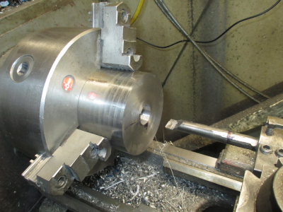
Press Feeder

I got a little more work done. Trying to setup and run two machines is a little taxing, and the lathe parts run is the priority right now. The press feeder is more of a fill in at the moment..... Until it becomes a panic. :)

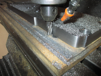
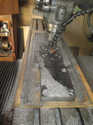
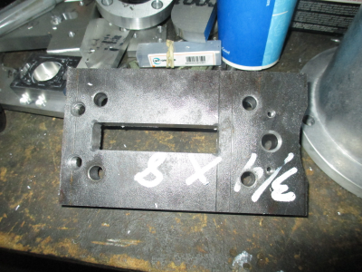
This is the slide plate that holds the pressure roller. You'll see how all of this goes together later. It was a little exciting going 3/4'' deep in steel with a 1/8'' end mill to do the finish profile to clean up the corners in the center slot. The bulk of the material was removed with a 3/8, 4 flute carbide endmill.
1583692890063.png

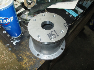
This is the bearing housing and adapter plate for the motor adapter.
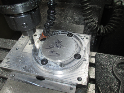
1583693079133.png

And one side finished along with the adapter (purchased from McMaster).
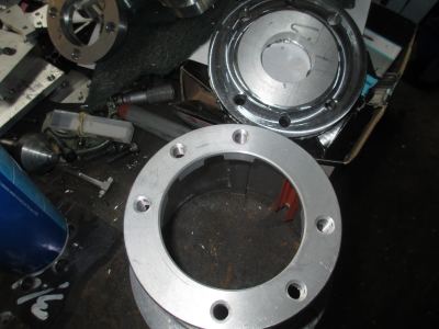
1583693134576.png

And it fits :)
1583693259970.png

Now I have to flip the bearing housing over and machine the bearing pocket. So this requires a clearance pocket in the fixture plate. This pocket also locates the part exactly on the center so I don't have to re-zero.
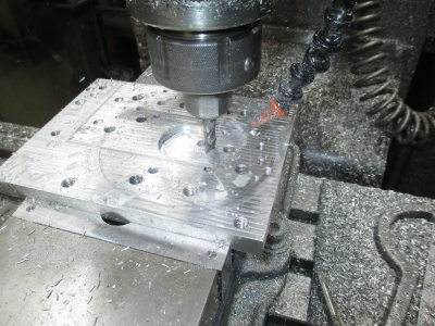
1583693498087.png

Or at least it should work that way. I'm having a bit of a problem with my machine: When cutting a circle, my Y axis dimension is always 0.002 smaller than the X axis dimension and this problem is getting worse, it used to be 0.001'' difference. When cutting a rectangle, the X and Y dimensions are always correct to +/- 0.0001''. I can't find any backlash in the system, and the math that calculates the circle seems to be correct in the program. I suspect a servo tuning problem, but not sure. I need to take a deep dive into this to figure out. For the moment, I can bore the critical dimensions to the correct size in a second operation, I left them undersize to accommodate the known error.
 
Haven't updated in a few days.

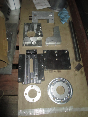
I finished up the secondary operations on most of the parts so they are complete. Just need to bore the bearing bores to final size, this will be done on the lathe. I'll be starting on the turned parts in a day or so, just need to finish up the mill work.

So here are the completed parts. The vise was on the machine when starting this project so I did all of the work that could be held in the vise first.
1584159989784.png

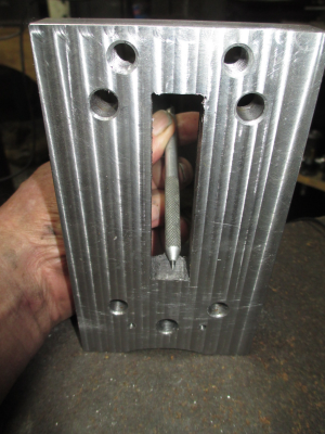
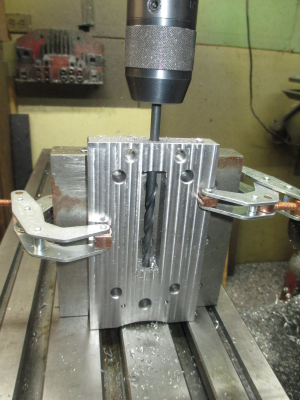
First today I need a 5/16-18 hole tapped at about where the point of my scribe is. A little tricky to drill & tap a hole in that location so is going to require some special tools.
1584160241610.png

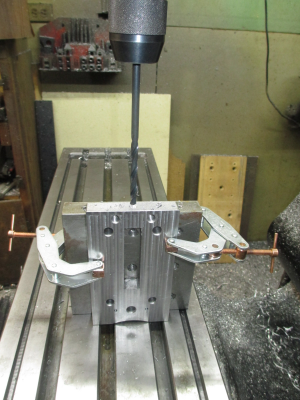
So set up on the angle plate and grab a long tap size drill bit. This is about the lower limit of my table, and the 5'' of quill travel is about 1/2'' into the work.
1584160602290.png

So get the drill bit started in the hole, then raise the knee to finish. I went down until the chuck just about touched the work., I don't like short holes when tapping, I want lots of room where possible.

1584160821500.png

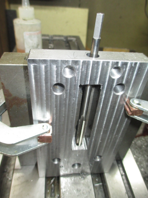
After drilling the top hole to size, clearance for a 3/8'' screw, I thought I was going to use this tap. But it turned out that the tap would not even get a good start in the hole without getting tight, and I wasn't about to force it. Don't need a broken tap in a blind hole and in the bottom of a slot. So find plan ''B''
1584161082103.png


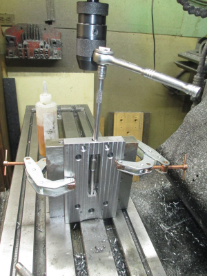
The tap looked fine and felt sharp, not sure what was going on with it. So the next step is to figure out how to extend a standard spiral point tap so I can turn it. A 5/16 tap has about a 1/4'' square drive end, so a perfect fit for a 1/4 drive socket extension. My 1/4'' drive socket extensions would not fit down a 0.400'' hole and I couldn't find a short one the I could get in there, and I wasn't about to modify one of my good extensions. Nor could I find a 12 point 1/4'' socket. So into my misc. tool drawer to find something that would work.

This is a bunch of mostly cheap wrenches, as well as duplicates that I have collected over the years. I couldn't find a 1/4'' drive extension, but I did find a 1/4 drive, 1/4'' 8 point socket. OK, now I'm in business, got the hole tapped. All this hole does is hold a 3/8 headless shoulder screw for use as a guide pin.

1584161928709.png

Then onto the next setup, the main mounting plate. A big ugly 1'' thick chunk of steel roughly 6x19''
1584162591752.png

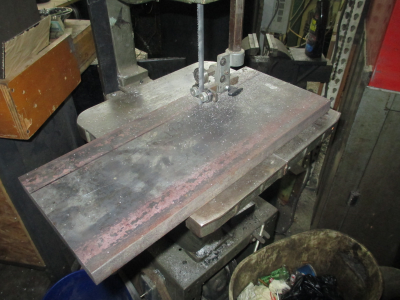
First order of business is to cut it down to 6 1/4'' wide from the original 8 inch wide. My old $25 bandsaw got a bit of a workout today. It really didn't take that long to do, about 15 minutes, even with a tired blade.

1584162908022.png

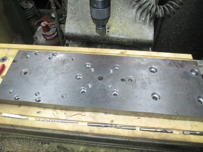
Then over to the mill to make swiss cheese out of it. All drilled, tapped, and counterbored as needed.

1584163060499.png

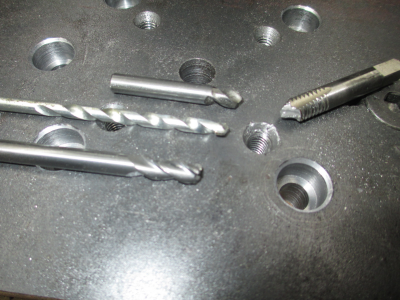
This was not without some frustration. Broke a 5/16-18 tap buried about 3/4'' into a hole.
First I tried a punch to try to turn the tap, it turned about 1/4 turn and just stopped. I figured it would do that.
So next I tried a worn out solid carbide spotting drill, it kind of wore a divot in the top so I had a bit of a guide for the next try.
A carbide masonry bit just wanted to walk to the side, so that didn't work.
So I grabbed a 1/4'', 3 flute, solid carbide endmill (bottom tool in the picture), and managed to chew through the tap. Even saved the threads, and didn't hurt the endmill much either.
1584163217212.png


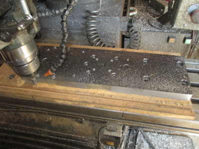
Tomorrow I'll do the milling on the plate, and that will finish it up. Then only one more piece to do on the mill, and then do some turning work and I can put it all together.
 
Last edited:
Those clamps always show up in the worst places Jim ! :grin: Pretty cool hitting them at 400 ipm in a rapid move and knocking an inch or 3 off your end mill . :bawling:
 
OK, moving right along.....

I finally found time to fire off the mill again and rough out the outside profile and bearing pocket in on the main mounting plate. One thing of note is that I took a cut with a partly worn out roughing endmill on the one edge that was so far untouched and had the original finish. I did this to preserve my new rougher that I intend to use for the roughing work, it would have been damaged by the mill scale on the first pass.

The mill scale on hot rolled steel is like carbide, really hard on tools. So I took about a 0.050 width of cut by the full 1 inch depth and cut in the conventional direction rather than a normal (for CNC work) climb cut. This allowed the tool to get under the scale and approach it from the back side so the tool was not trying to dig into the scale as the tooth approached the work. A couple of other ways of removing the mill scale is to simply saw off the edges or by grinding down to bare metal. In this case, I'm leaving the mill scale on the front face because I want the hard surface for an anti-wear bearing surface, and on the back side it doesn't matter anyway.

First pass with the rougher, 1'' DOC, 0.050'' WOC, 1/2'', 4 flute, cobalt roughing endmill, 94 FPM (about 740 RPM), and about 0.0019 feed / tooth, 5 IPM.

1584332520142.png

And cutting the indents. The indents are really only for appearance in the finish part, no useful function. Same cutting parameters as above.
1584332696715.png

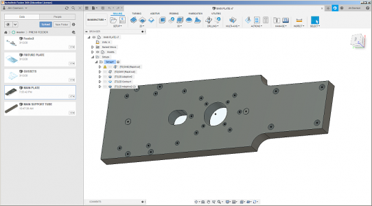
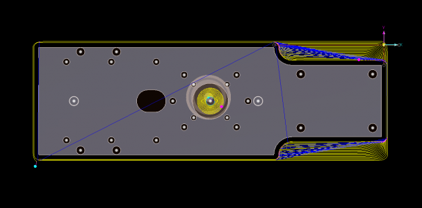
Here are the tool paths, each yellow line represents one pass and is the center of the tool, the blue lines are rapid moves. 0,0 is the top right corner, at the edge of the raw stock, and this was a mistake on my part as you'll see below.
1584333103888.png

And the outside rough profile finished, I left 0.020'' on each side for finishing. And have moved over to rough out the bearing pocket. About 90 minutes of cutting time so far.
1584333554907.png

Same cutting parameters as above except for the DOC was set to 0.300 to allow for chip removal with the mist coolant system. I didn't want chips packing in as they would have done had I gone the full 1'' DOC.

Now comes the fun....... POWER FAIL :eek: for about 1/2 hour. And the only time I lose my zero is on a complete power down.

Yup, as I said above I put the 0,0 in the wrong place, that point is gone, it's in that pile of chips. :bang head: Worse yet is I'm not even exactly sure where any feature is at relative to the existing edges because they are not finished and are of a bit indeterminate size because the end mill was a bit smaller than 1/2 inch and the material was cut ~1/8'' oversize all around and I zeroed on the raw edges.
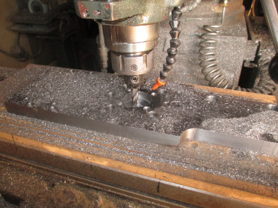
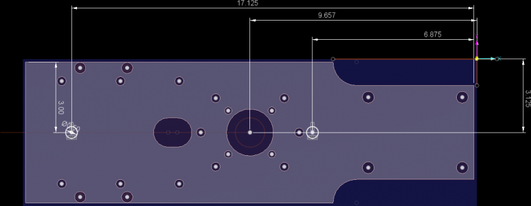
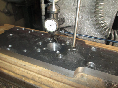
What could I have done differently? I could have put a small divot in the part at a known location with a center drill when I was drilling all of the holes and used the pointy end of the edge finder to locate that divot. I could have relocated in a couple of minutes.

This is the position that a power fail left the tool in............. So how to zero on a point in space?
1584334182413.png

So back to the drawing and locate the bearing pocket from where the computer thinks it is.

1584336612610.png

Which is located at -9.657, -3.125, so now all I need to do is locate the center of the pocket and plug those numbers into the program. So bring out the Blake center indicator, and warm it up in front of the heater. It doesn't like to work when its cold. Found the center, plugged in the numbers and I'm back running.
1584337154423.png

By this time it's about 7:00 PM, so I'm done for the day. Tomorrow I'll finish cut the outside profile and finish bore the bearing pocket, then this part will be complete.
 
Last edited:
I got one chunk of iron off of the table and time to load another. Need to make a few holes. Didn't get a whole lot done today on this project, had to do some programming work, and then to set up the lathe for the next run.

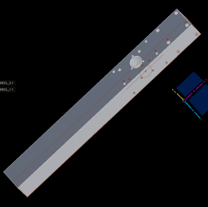
I put all of the holes on one side of the drawing, but they will actually be on 3 sides, but all relative to the same 0,0 point. Just makes easier to do one CAM setup.

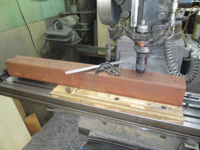
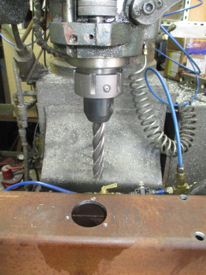
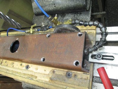
The most fun one will be the two inch hole. It has to align on both sides of the 4 x 4 x 1/4 wall tube, the rest of the holes are just drilled & tapped in one wall. I'll do the 2 inch hole from one side, probably with a long endmill. Drill first, then run a pocket routine. I could use a hole saw then bore, but I don't have a good way to hold the holesaw arbor. Keyless chucks can be destroyed by over torque and a hole saw is way over the chuck's capacity. I have one on the bench that was damaged that way, not sure if I can fix it. I don't have a keyed chuck for the mill, guess I should buy one.
1584417771347.png

About 39 inches long, pretty much takes up the whole table but all of the work is within about a foot of the end, just need room to support it.

1584418032195.png

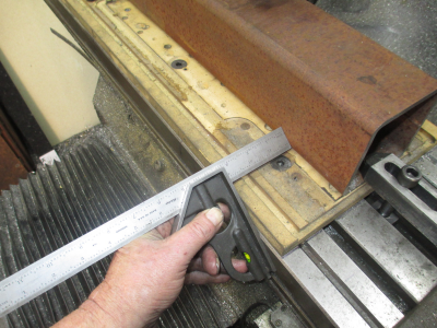
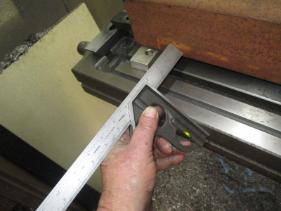
Since there is nothing critical in the hole locations except that they need to be relative to each other, using a square to align to the table is close enough, this normally gets me within a couple of thou. No dialing in required.

Just move the scale to the work and lock the screw. And snug the clamp down.

In the upper left of the picture, you can see the magnetic scale coming loose from the table. This has been on there since 2014. I spilled some MEK in that area about a year ago, other than that, the tape seems to be impervious to any coolant and way oil. I have some new strip I'll install when this project is complete. Only takes about 15 minutes to install.
1584418759772.png

Then move the other end to the scale and snug that clamp. Check the first end again and tighten the clamps.
1584418886609.png
 
Got the holes done on one face of the tube before I had to set up the lathe again.

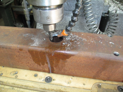
The 1/2 and 10-24 tapped holes went fine, then was time for the 2 inch holes through both faces. That took a bit of thought. I decided to go with the long end mill method.

First I drilled through with a 3/4'' drill just to get a starter hole. Then machined the top hole with a 3/8 solid carbide, 4 flute end mill.

I since I haven't made the mating part yet, I decided to make the top hole 2.062 rather than 2 inch. This will give the long endmill some clearance on the shank when doing the bottom hole, and allow easier insertion of the mating part.
1584505495404.png

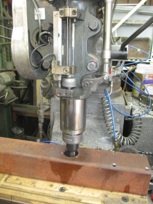
So now it's time to pocket the bottom, so out comes the 3/4 inch, 4 inch cutting length, 4 flute. This pretty much used up all of the quill travel I have.

1584505807662.png

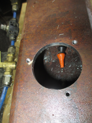
I rigged the coolant up inside of the tube so I could get it where it would actually do some good.
1584505914215.png

And the inside view
1584505958864.png

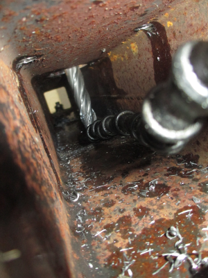
And away we go, running a pocketing routine. Spiral down in the center, then 0.050'' DOC and 0.050'' step over. Not much quill travel left.
1584506987503.png

An an inside shot, that's a lot of endmill hanging out there. :cautious: But everything went smooth with minimal chatter.
1584506302253.png

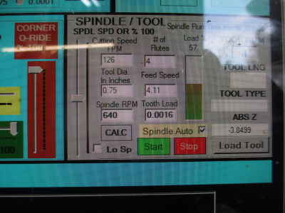
And a screen shot of the cutting parameters.
1584506375310.png

I'll get the other 6 holes drilled & tapped tomorrow then that will end the mill work, other than possibly some minor adjustments on this project.

Then it's over to the lathe to make a few pieces.

Stay tuned..........
 
Last edited:
Finished up that big ugly 4x4 tube this morning and that completed most of the mill work on this project.

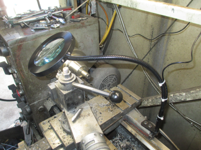
So over to the lathe to make round things. The other day I did a quick install of a new magnifier lamp for the lathe. Well, it was a little too quick, kinda had a small problem :eek:
1584588319097.png

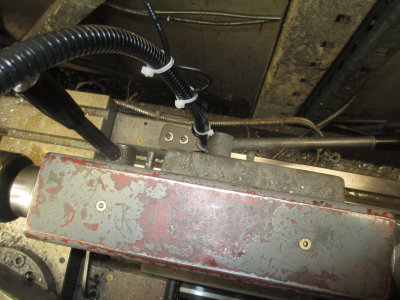
I didn't check for clearance between the lamp mount and the tailstock. OOPS. :bang head:
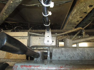
1584588448160.png

So rotate the bracket 90 degrees and fixed for the moment. I think I need to do something else here, not sure if I like this mount. We'll see by the end of this job.
1584588537163.png

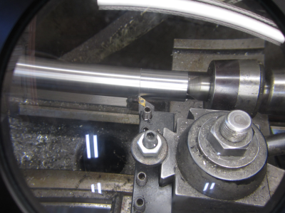
The view through the magnifying lamp, actually works pretty good. This is about what it looks like to me also. Much easier on the old eyes.
1584588847132.png

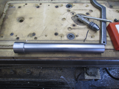
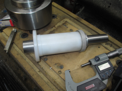
First I turned down a chunk of 1 3/16 steel to 1 inch, leaving 1 inch of it at 1 3/16. Normally would not even be noteworthy but it is a part of the project and has a dual use as a fixture.

The finished shaft that will double as a stub arbor for the next part. About 8 1/2 inches long
1584588957235.png

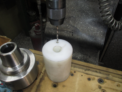
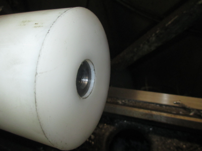
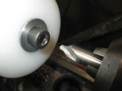
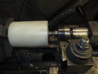
So the next part is the bushing that the shaft rides in, 4 inch UHMW. I drilled and bored through for a 0.002 clearance fit on the 1 inch shaft. Now I have to turn the OD to 2 inches to fit the hole that it goes in. And the OD needs to be more or less concentric with the bore which means I need to mount it on an arbor to turn the OD. This is where the above shaft come in.

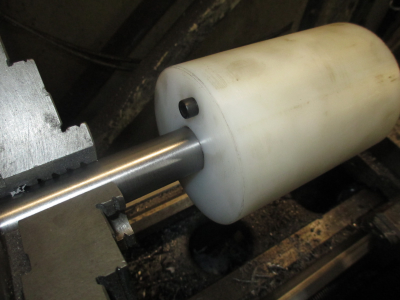
First drill & tap 1/4-20 for a drive pin (1/4-20 screw).
1584589407671.png

Then put the shaft in chuck and drill & tap the end for 1/2-13. Then slide on the UHMW with the drive screw in it.
1584589548470.png

The drive pin engages the chuck jaw to turn the part.
1584589615896.png

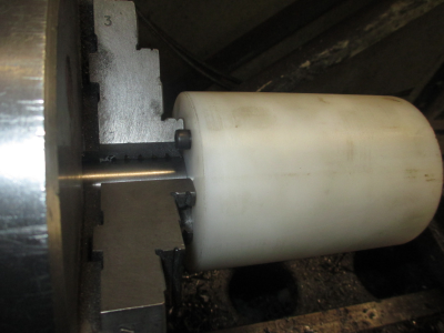
I chucked the shaft just a bit short of the length of the UHMW so the end screw would hold it to the chuck jaws.
1584589740881.png

Then center drill the screw a bit to get a decent center
1584589823779.png

And ready to make piles of nasty UHMW stringy things.
1584589895114.png

That's all there is for today...... stay tuned for more.
 
Finished up the UHMW bushing and bored the timing sprocket that will live on this shaft.
1584675024004.png

Then faced and bored the drive roller.
1584675093639.png

And because of many other tasks, this is all I got done today on this project. I'll finish the drive roller tomorrow, and get the main drive shaft completed. Then back onto the mill for a few odds & ends that need to be finished. Maybe I'll get the stand welded together and painted over the weekend. Then when I get the aluminum parts back from anodizing (Monday maybe?) I can start assembling.
 
Back
Top