POTD- PROJECT OF THE DAY: What Did You Make In Your Shop Today?

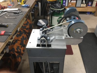
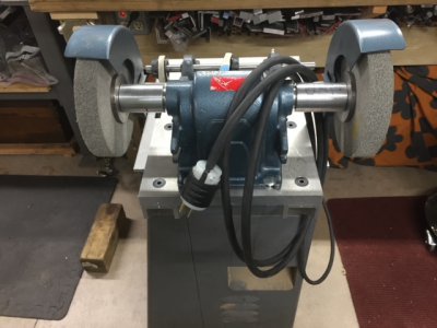
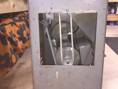
I don't think you're going to need to fabricate an adaptor plate. I used the same stand to build a deburring wheel setup earlier this year. I went to Home depot and purchased a weatherproof outlet box like this:


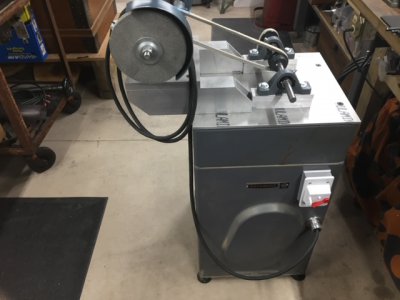
In my case I also needed an extension like this because the switch I wanted to use was too deep for the box


I mounted the box inside the stand and the extension on the outside. and used a weatherproof toggle switch cover like this.


You might want to consider something similar. If you intend to grind metal you don't want it getting into the switch or motor, In my case I have a TEFC motor mounted inside the stand.

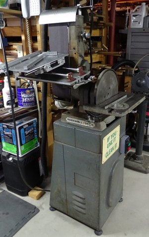
Here are a couple pictures. You can see the box mounted to the inside of the back wall in the first picture, and the extension and switch cover in the 4th picture. I used the same setup on my Delta/Rockwell disk/belt sander as seen in the last picture. I got lucky on both machines. The existing bolt holes matched the pattern of the boxes and extensions. I didn't even have to drill a single additional hole.
 

Attachments

  • IMG_1251.JPG
    IMG_1251.JPG
    88.8 KB · Views: 52
  • IMG_1252.JPG
    IMG_1252.JPG
    106.3 KB · Views: 44
  • IMG_1253.JPG
    IMG_1253.JPG
    94.7 KB · Views: 43
  • IMG_1254.JPG
    IMG_1254.JPG
    84.4 KB · Views: 50
  • DSC00029A.jpg
    DSC00029A.jpg
    440.5 KB · Views: 51
I don't think you're going to need to fabricate an adaptor plate. I used the same stand to build a deburring wheel setup earlier this year. I went to Home depot and purchased a weatherproof outlet box like this:


In my case I also needed an extension like this because the switch I wanted to use was too deep for the box


I mounted the box inside the stand and the extension on the outside. and used a weatherproof toggle switch cover like this.


You might want to consider something similar. If you intend to grind metal you don't want it getting into the switch or motor, In my case I have a TEFC motor mounted inside the stand.

Here are a couple pictures. You can see the box mounted to the inside of the back wall in the first picture, and the extension and switch cover in the 4th picture. I used the same setup on my Delta/Rockwell disk/belt sander as seen in the last picture. I got lucky on both machines. The existing bolt holes matched the pattern of the boxes and extensions. I didn't even have to drill a single additional hole.

YES! That's exactly what I need to do...

I'll study on that and see about ordering the parts.

Thanks!

-Bear
 
@projectnut

In your photo of the 12" disk/6" belt sander, I'd like to learn more about the sliding table set-up you've got there.

Is there a build thread on it?
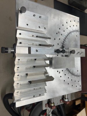
There may be a couple blurbs in some posts where I was asking questions, but there isn't a complete thread on it. It's a HSS lathe tool sharpening fixture I've been working at and improving over time. It was originally built to sharpen tooling for threading. Rather than continually guess at whether or not I was getting a 60* point I made the fixture to be certain. Over time it has been expanded to include left and right cutting tools and some form tools.

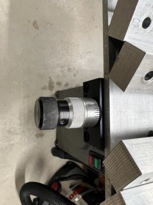
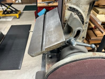
It's just a base plate that has Thomson rods and bearings supporting the moveable fixture plate. The fixture plate can move left or right and forward and back. The table on the sander can be adjusted to provide relief on the lower sides of the tool. The plate also has a micrometer type adjustment on the rear to allow more precise stock removal. It's still a work in progress and probably will be for some time since there are more pressing projects in the works.

As it sets now it can sharpen 3/16", 1/4", 5/16', 3/8", 7/16", 1/2", 9/16', and 5/8" tooling. As time goes on, I continually make changes and improvements. If anyone has more interest, I can take some pictures and do a write up.
 
Today i bought me some used tires for the 605. Also the white elephant no: 2 has left for the paint shop, so i got the 605 in the big garage and test fited one of the tires. The tires are of an astra H but the bolt pattern and offset is to close they fit. I have to switch to tapered bolts which isn't any problem. I was going to buy only 2 new 15" tires but the back one have tread but are 15 years old and cracked so i need 4, the prices have gone up so high it was going to take my entire paycheck. So i found this set of 5 used 16" tires and rims 3 almost new less than 100 km on them still have the little nipples and the seller included 2 more at 50% life. All for 100$ so for the first time in years i'll be driving steel wheel on my car in the winter, i'm debating should i paint the rims mat black and drive them like that or should i just buy hubcaps and be like everybody else.
The 605 also got a sticker to put fear in everybody behind it, it has a 12 valve in it :laughing:
IMG_20220826_122208.jpgIMG_20220826_122157.jpgIMG_20220826_173829.jpg
 
@projectnut

Your sharpening fixture looks like very useful tooling to have.
I'd definitely be interested in some more pictures of it.
Particular interest in how it attaches to the sander's table and the various adjustabilities.
Are the linear bearings plain bearings or ball type?
 
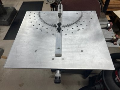
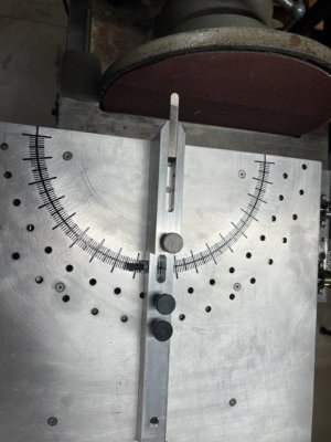
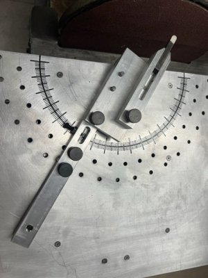
Looking a little closer at the sharpening fixture in my last post I can see it's an early prototype. The most recent version is a little more finished including the degree marks milled into the top plate and a few more recent accessories.

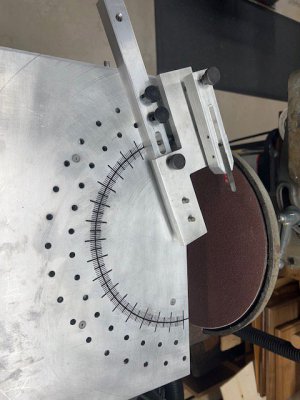
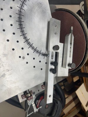
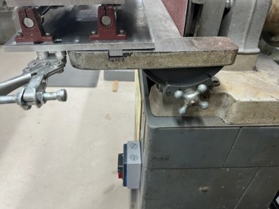
For the record this "project" has spanned several years. It started as a simple fixture to be sure i was getting the correct angle on tooling meant to thread various size blanks. Since then, it's morphed into a tool that can create either left- or right-hand cutting tools, and most recently some form tools. The base is 3/8" aluminum plate with a 1/2"x 3/4" steel strip bolted to the underside. This strip locates the fixture on either the tabled for the disk or the belt. A Destaco clamp on either side secures the base to the table. Mounted to the top side of the base are 4 Thomson linear ball bearings. These bearings support the rods that allow the left to right movement of the table.

Mounted to the underside of the top plate are 4 Thomson bearings that support the rods that allow the forward and reverse movement of the table. There are shaft collars mounted on each of the forward/reverse rods to limit the free forward motion of the table and prevent the tool from crashing into the disk or belt. There is a micrometer style adjustment block at the rear of the table to allow slow and precise feed adjustment. When in use the base is mounted flush with the top surface of one of the tables. In the current pictures I just set the fixture on the disk table for photos. The tables themselves are adjustable to the face of either the belt or the disk. This adjustment provides the top to bottom relief angle on the tool when grinding. The most common relief angle used is 7*, but I have been known to go as high as 15* for some applications.

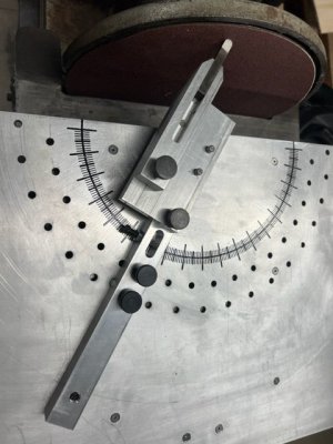
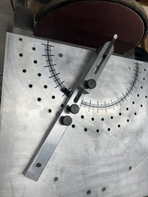
The top plate is 1/4" aluminum plate. There is a hole drilled in the center left to right and 1" from the edge that faces the belt/disk. This hole is the pivot point for the tool holder base and the center point of the degree wheel. The degree wheel has hard stops every 5*, and the tool holder base can be clamped in place at any graduation within the 180* span. Degree graduations were cut into the plate using either a 1/16" or 1/32" end mill. The longest widest graduations are at the 10* marks (10*, 20*, 30*,40*, etc.). The shorter wide graduations are at the 5* marks (5*, 15*, 25*, 35*, etc.) The shortest narrowest markings are at single degree increments. All degree marks have been highlighted using a black paint marker from McMaster.

The tool holder base pivots on a shoulder bolt in the afore mentioned hole at the center of the plate 1" from the disk/belt. There is a slot in the tool holder base that aligns with the degree markings. There is a pointer drilled and tapped into the side that when properly adjusted will align the tool with the corresponding degree marking on the scale. There are 2 spring loaded detents in the base that align with the hard stop holes in the top plate. Either can be engaged or disengaged by turning the top knob 90*.

In the top of the tool holder base about an inch from the rear there is an adjustable roller ball that keeps the tool holder base parallel to the top plate without rubbing on it. Unseen in these pictures are the 2 dowel pin holes and the threaded hole that align and secure the tool holder to the base.

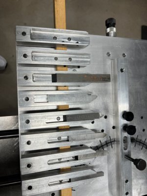
The tool holders themselves are nothing more than aluminum flat stock that has a pocket milled to fit the appropriate size tool. The tool is secured to the holder with 2 set screws drilled and tapped into the side of the holder. There are 2 dowel pins flush with the bottom of the tool pocket that extend through the holder and into corresponding holes in the tool holder base. Near the rear of the tool holder is a clearance hole that allows the threaded shaft of the grip knob to pass through and align with the corresponding threaded hole in the tool holder base.

The other 2 attachments allow the tool holder to be positioned offset to either the left or the right of the tool holder base. As you can see in the photos the one isn't completed. The dowel pin alignment holes and the threaded hole for the grip knob are yet to be completed. At this point the tool holder is just sitting on it.
 

Attachments

  • IMG_1442.jpg
    IMG_1442.jpg
    100.4 KB · Views: 36
  • IMG_1443.jpg
    IMG_1443.jpg
    60 KB · Views: 38
  • IMG_1447.jpg
    IMG_1447.jpg
    58.2 KB · Views: 31
  • IMG_1446.jpg
    IMG_1446.jpg
    57 KB · Views: 32
  • IMG_1444.jpg
    IMG_1444.jpg
    54.6 KB · Views: 33
  • IMG_1448.jpg
    IMG_1448.jpg
    57.2 KB · Views: 33
  • IMG_1450.jpg
    IMG_1450.jpg
    66 KB · Views: 34
  • IMG_1451.jpg
    IMG_1451.jpg
    71.2 KB · Views: 33
  • IMG_1452.jpg
    IMG_1452.jpg
    61.7 KB · Views: 33
  • IMG_1453.jpg
    IMG_1453.jpg
    49.5 KB · Views: 31
  • IMG_1455.jpg
    IMG_1455.jpg
    108.7 KB · Views: 28
  • IMG_1457.jpg
    IMG_1457.jpg
    142.4 KB · Views: 41
Last edited:
Finally recovered from the bum holes I drilled in my lathe casting mounting my stepper motor for a homebrew ELS. The fix involved welding on drill bushings to guide the holes. Got the stepper mounted as well as the rotary encoder. Hope to get to wiring soon.
PXL_20220909_210239636.jpg
Ran the lathe at 400 RPM just to check the encoder belt tracking and things seemed good.
 
Back
Top