Optical comparator LED Upgrade.

The XM-L3's I picked up were on a copper heat spreader, but same difference. Sounds like you have a current regulated bench supply, that's all you need to test out the concept.

Mounting and measuring the correct position is certainly one of the more important parts. Much more important for the contour light, less so for the surface light.

If you haven't ordered LED's yet. I'd grab an XHP-50.3 or two to test out for the surface light. I think the extra lumen output will be helpful with any magnification over 10x. The cross (or dead spot) between the dies shouldn't show up on the surface light optics.
Glad I checked this thread again, was about to order :) I'll get a few of each.
And now the waiting begins,,,,,

Tku
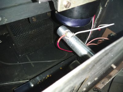
 
And now the waiting begins,,,,,

Even expedited shipping is kinda slow!

Just for fun I lined up a bunch of leds on stars.
The order is XHP70, XHP50, XM-L3, XP-L2, XP-G3, and XT-E.XHP70   XHP50.2   XM-L3   XP-L2   XP-G3   XT-E.jpg

On the leftmost two (XHP70 and XHP50) you can just make out the four dies, or LED chips that make up the LED. I was concerned that cross would show up in the middle of the screen (you can see it's effect in a parabolic reflector at close range).

The third one in is the XM-L3. The active LED Die is ~3mm x 3mm. That matched the size of the filament of my bulb.

The last two are small die format LED's (XP-G3 and XT-E) that might improve the contour light focus. With the collimated (spelled correctly auto correct!!!) lens, it might, just maybe, improve edge sharpness. I've yet to try them out. Less light output on that light probably won't hurt anything.

In terms of light output:
XHP70.3 ~ 5500lm
XHP50.3 ~ 2300lm
XM-L3 ~ 1700lm
XP-L2 ~ 1200lm
XP-G3 ~ 900lm
XT-E ~ 650lm

Even the lowly XT-E will be pretty close in total light output to a 70W projector style bulb. The XHP70's, are just plain stupid... ...and they're awesome in a flashlight!

Anyway, If anyone is wondering what these look like side by side, this should help.
 
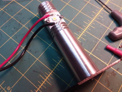
It's been a while, but finally got my LED's installed. I had ordered XHP50.3's and XM-L3's on 5050-20 mcpcb mounts.
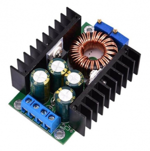
To start I decided to use just the XHP's after my first test. I am using XM4016 power supplies set to 11.9vdc and .4A current limit. I think I can increase the current to >1000ma but no reason to at this point. Light output is more than adequate compared to the filament bulbs. I might not bother with making the surface light adjustable.

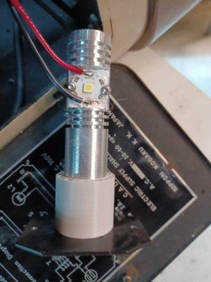
One unexpected problem (not yet solved) is that the copper back of the MCPCB is not isolated from the LED when power is applied. When the LED is lit, there is 5vdc between the copper back and ground. While this has little effect if you only mount 1 led, since I have 2 they both light up regardless of which one I power! (this is through the frame of the machine joining the 2 electrically)

I'll have to figure out a way to isolate the MCPCB's while still having them mechanically secured. I will probably 3D print something to separate the aluminum heatsink from its bottom mount.
Except for that I am very very pleased with the results. Thank you for starting this process off.
 

Attachments

  • 20220228_192622 (Small).jpg
    20220228_192622 (Small).jpg
    81.9 KB · Views: 16
  • 20220228_192609 (Small).jpg
    20220228_192609 (Small).jpg
    102.4 KB · Views: 17
  • IMG_20220222_134528 (Small).jpg
    IMG_20220222_134528 (Small).jpg
    98.1 KB · Views: 14
  • XL4016 module.png
    XL4016 module.png
    357.1 KB · Views: 16
@ub27Rocks

Thanks for the update.
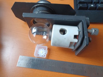
Can you show a picture of the original lamp/mount that you replaced with the LED?
It helps me understand when I can see the "before" state, as well as the "after" state.
 
One unexpected problem (not yet solved) is that the copper back of the MCPCB is not isolated from the LED when power is applied. When the LED is lit, there is 5vdc between the copper back and ground. While this has little effect if you only mount 1 led, since I have 2 they both light up regardless of which one I power! (this is through the frame of the machine joining the 2 electrically)

Nice! Glad it's coming along.

Now, for the 5V gnd issue. See the datasheet here: https://cree-led.com/media/documents/ds-XHP50.pdf
The XHP50's are designed for 6V or 12V operation. The wirepads on the LED and how to board is wired configures the voltage. Sounds like you have a 12V 'star' board. If you look at the above datasheet pp30-32, you will see the two recommended layouts. The center pad on bottom of the LED die is normally connected to the heatsink. In the 12V configuration they short that heat spreader pad the center of the diodes, setting the heatsink potential at 1/2 of the LED string voltage.

You could try the XLM's. Or make/print a fiber or insulating spacer to hold the LED heatsink you made floating from earth ground.

Let us know how you sort it out!

Dan
 
@ub27Rocks

Thanks for the update.
Can you show a picture of the original lamp/mount that you replaced with the LED?
It helps me understand when I can see the "before" state, as well as the "after" state.
The third photo with glass bulb and white mount is the original mount/assembly.
 
The solution was to shorten the al mounts by 15mm and place this 3D printed part under them. Everything is now as it should be.

Much more light than before, and no longer worried about burned out filaments.

Thank you again for the idea and support.
 

Attachments

  • IMG_20220301_132700 (Small).jpg
    IMG_20220301_132700 (Small).jpg
    49 KB · Views: 9
The third photo with glass bulb and white mount is the original mount/assembly.

Thank you.
More questions, please.

Regarding the lens assembly on the original lamp mount:
Is the lens assembly deleted or are you going to figure a new mount for it?
What is/was the function of the lens assembly?
 
I only replaced the light bulb and its mount with an LED. The LED arrived on a 20mm diameter plate which I attached to an aluminum upright. It was designed to place the 3mm square led itself in the same place as the 3mm square filament of the bulb.
The shadowgraph/comparator has 2 lights, one for shadow/profile work, the other for surface lighting.

The lenses are still needed, they colimate the light and make it into a more focused beam. The reason for the replacement is to a) remove the worry about a US$50 bulb buring out while in use. That would cost me an extra US$35 to ship to Canada. the LED is US$6 and is not likely to burn out in my lifetime. The side benefit is that the LED generates almost no heat, the bulb heats the first lens and generally bakes dirt on to it.
 
Back
Top