Need help with a VFD for my mill

Bill,

Nice work! Are you a machinist or a machine maintenance technician?

Harvey
(A CNC tech many years ago.)
I've been retired for 7 years Harvey (freedom 55!). My training is engineering, but my career was management in a large fortune 100 company. Now that I'm retired, I spend a lot of time on the golf course. I consider myself a self-taught "hobby machinist" and have the luxury of a fully equipped machine shop that I play in when I'm not golfing. Mostly making or repairing parts for my hot rod buddies when we are restoring old muscle cars. Or refurbing old industrial machines. My most recent project was my '52 Monarch 10EE lathe. I love making parts on that thing! Like is good! Cheers, Bill
 
Last edited:
Bill that picture of the inside of the panel is very helpful. Do you have a fuse block ahead of all the electronics for protection?

I was also thinking about adding a 220v to 110v transformer to power a coolant pump, and work light. Bill, Dan what are your thoughts on this idea? Is there another way?

Brian, the VFD is fused. Half of what's inside the control panel is low voltage signal wires to/from the VFD. I can't recall if the tachulator board had a replaceable fuse on it or not.

The other half is 120v wiring to power the receptacle inside the box (tachulator), the receptacle on the rear of the box (DRO, x-axis table motor, & z-axis knee motor), the hour meter (top left inside the box), chip vacuum, the 2 Dazor machine lights and all the pilot lights in the switches.

The main 240v power feed to the mill is routed first to the "Power" switch in the panel and from there feeds the VFD. So by breaking those two 120v input lines with that switch, it effectively kills all power to the VFD without fiddling around with multiple on/off switches.

You don't need a transformer to power your coolant pump. Your 240v input consists of two (2) 120v feeds. As long as you also bring a white "common" wire into your panel, you can power any 120v appliance with one of those 120v feeds + your common. Simple as that. Bill
 
Awesome Bill! If I am ever in Canada I'll buy you a Molson!

Sent from my SCH-I535 using Tapatalk
 
O.K.

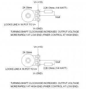
Dan this pot and resistor setup sounds great! Would you mind elaborating on the proper resistor needed, and how the wiring is configured?

Sure - here is what I'm talking about -
POT WIRING.jpg
Does this make sense to you? I didn't draw the switch I mentioned (too lazy to add it tonight), but I can add it if I need to later

POT WIRING.jpg
 
Sorry I didn't respond to your reply sooner. The drawing is very helpful!!

Sent from my SCH-I535 using Tapatalk
 
Got another question. Where should I have the belt set on my step pulleys? I'm thinking the middle range. If this is correct should I be able to leave it there and forget about it? One reason I am asking is so I can determine a location for my tachulator sensor.

Sent from my SCH-I535 using Tapatalk
 
Today I temporarily hooked up my VFD to the mill. Gladly everything seems to be in working order on the machine! I was going thru the settings and getting familiar with the drive. What I did find out is that I will more than likely need a breaking resistor to stop the machine. I kept changing the deceleration setting till the drive tripped and could not get below 4.75 seconds from 1100 r.p.m. I will still wait to buy one till I get the machine wired the way I want because it will be easy to add afterwards.
 
I'd leave the belt change system so you can swap belts over easily. It's true that a VFD allows you to cut down on belt changes but you shouldn't operate the motor for long periods under load at low speeds as it won't cool as effectively. Also, if you run at half speed, you are limited to half power. Similarly, if you run above base speed (whatever the rated speed is at 60Hz), you will not be able to develop full torque so power will be reduced there too. However, if you are doing low power work, it's handy to be able to vary the speed down to 20% or so (to use an edge finder for instance) and bang the speed up a bit higher for a small drill without changing belts.

I use my VFD to vary the speed all the time but I also change the belts and backgear to get the speed roughly where it should be. I wouldn't mind a Tachulator but for now I just set the closest speed on the lookup table with the belt and then change the VFD up or down slightly to get it more precise.

And BTW - check your VFD manual to see if it does "DC Current Injection". This is a form of braking that doesn't require the inertial energy to be dumped in an external resistor. Instead it generates a high braking torque in the motor by applying a stationary current to the windings. Don't worry - that's how induction motors work anyway. But normally when a VFD tries to slow down a motor it regenerates electrical energy into the VFD which then needs somewhere to put it. If there aren't enough losses going on in the VFD, it will either trip to protect itself or limit the ramp. DC injection may not get you quite the same deceleration as a large braking resistor but may still be a big improvement without the complication. And many VFDs don't have the option to add a braking resistor anyway. You can set the current at about the same as the current on the motor name plate.

Murray
I'm probably not doing it right but I set the VFD on my Mill at 60Hz and leave it there. I vary the speed on the mill by turning the variable speed knob. On my Bench mill I have put the belts on the slower speed and there by I run the VFD up the scale on Hz so I'm not dragging it down on low RPM. As for the small lathe I have a pot and am changing speeds so often that I leave the belts on the middle pulleys. My luck seems to be holding out as I've not had any problems. (yet) Because of a recent turn in health problems, I'm not able to work in my shop as I would like to and may have to resort to selling my equipment off.
 
Back
Top