Need help with a VFD for my mill

Were do you guys buy your enclosures from? According to the Hitachi manual I need a minimum 9"w x 13"h x 7"d enclosure to house the drive.
I've bought them off eBay, CL and Kijiji. But mostly I get them (for scrap metal prices) from my local metal recycling/scrap yard. I drop in there every once in a while and wander around for a half hour. Almost always I'm able to pick up a few that aren't full of holes and sometimes they even come loaded with (expensive) Allen Bradley 800-series switches like e-stops, start buttons, selectors and pots. Bill
 
Last edited:
I will have to try that. I will go to the yard where my machines came from


Sent from my SCH-I535 using Tapatalk
 
I just bought a new Baldor AC MICRO DRIVE VFD comes complete with FWD & REV and RPM knob"Brand New Model " Easy. Love it I mouted it next to my Off and On swithch, I used a small 1/4' x 2"X 12" alum plate as a bracket, used the same wire that came with the Mill. I just dropped out (1) wire from the cord for the single phase in and

http://www.baldor.com/support/Literature/Load.ashx/BR760?LitNumber=BR760

I got the one on pg 6 on the left. Its about 6 x 9 and light.

I called Baldor super easy 347.30 + 18 shipping= $365.30
[h=1]BALDOR Part Number VS1MX81-2D[/h]
 
That bald or drive looks very nice! I already bought a Hitachi drive though. I will keep that in mind for the future. if there drives are as good as there motors they should be top notch!!
 
It's called a Tachulator Module, made by Trexon.com in Toronto. You can buy them also from LittleMachineShop.com. About $100.

It works awesome with readouts for RPM and also SFPM if you enter the dia of the piece you're working on. Bill

Nightshift,

I checked out the Tachulator. Where and how did you mount the black/white encoder disk and the photo sensor?

Harvey
 
Last edited:
Were do you guys buy your enclosures from? According to the Hitachi manual I need a minimum 9"w x 13"h x 7"d enclosure to house the drive.

I used to be able to go to the scrap yard and pick up a ton of things for scrap prices. They've since stopped letting people do that. I now have to resort to the buddy system when I need something. I tell all my friend that are in construction or demolition what I am looking for and they usually can find it. Sometimes I have to wait awhile. If I need something now, I go to an electrical supply house but you have to pay retail for it. One of the most important things you can do locally is develop a network system with friends and don't forget CL.
 
Nightshift, I checked out the Tachulator. Where and how did you mount the black/white encoder disk and the photo sensor? Harvey
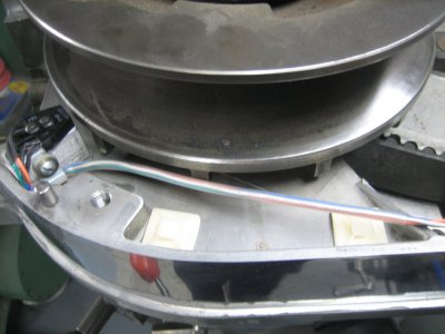
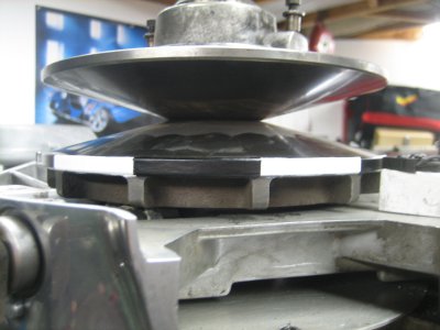
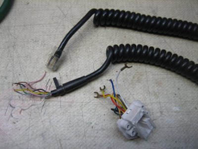
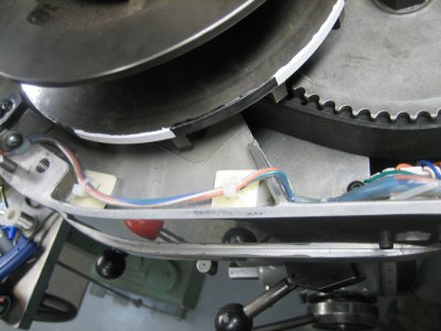
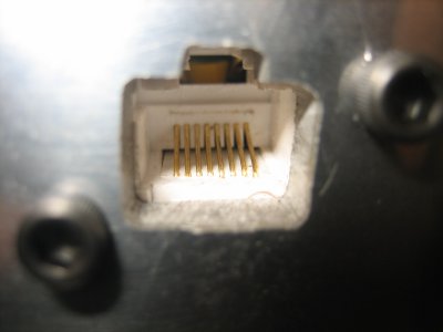
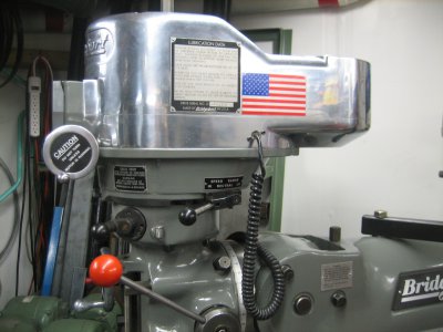
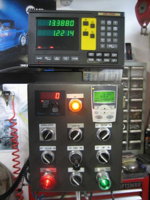
Harvey, here's a few pics to show you how I did mine. The sensor on the Tachulator is has both a photocell to pick up the revolution marks as well as a LED to provide enough light so the sensor can differentiate between light and dark to send pulses. I removed the motor and top head cover to gain access inside to the variable pulley assy. I made a little aluminum block to mount the sensor near the front right corner inside the housing with the sensor level with the flat face on the lower half of the pulley assy. Then made up a small wire harness to connect to a Cat 5 receptacle which I mounted in the lower pulley housing (after making the appropriate hole for the connector to attach from the outside). A Cat 5 cable has more wires than the 4 you need, so even a 4-wire phone cord would work. I didn't use the sensor disc they provided. Instead I painted the flat face of the lower pulley flat black. Then hand painted every other section around the pulley face in white. If I recall, this gave me 6 white and 6 black sections. When I wired up the coiled Cat 5 cable to the Tachulator inside my control panel, the 2 wires for the sensor LED are powered thru the Power switch to the Tach & DRO, which in turn is powered by the master Power switch (that powers the VFD). I did it this way so when I turn off the master Power switch, it kills power not only to the VFD, but also the Tachulator and DRO which obviously don't need to be on when your not using the mill. Hopefully the pics help you. Cheers, Bill

IMG_3041.JPG IMG_3049.JPG IMG_3044.JPG IMG_3051.JPG IMG_3053.JPG IMG_3057.JPG Mill Panel.jpg
 
Last edited:
Thanks, Bill, the pictures will help my own installation a lot.

Harvey
 
Next question..Resistance Braking. If I am reading the manual correct I need a 35 ohm resistor for the 2.2kw drive. My question is what is the correct wattage? IIRC I read , or someone mentioned to me 350- 500 watt.

We have a few machines here at work that have resistors from this place.

http://www.surplussales.com/Resistors/WireWound/WW30-499.html

We have one on a 1hp 3 ph hitachi drive but there is no wattage written on the part just the ohms.

I was looking at this model: (RWM) 26-136-35R $25.00 seems like a good price to me.

- - - Updated - - -

Bill Thanks for the wiring pictures of the tach.! They are very helpful!!
 
Back
Top