My Pair of South Bends - starting out now.

I think my green thing looks and quacks like a 9C. The shapes of the feet under the bed can give away the differences between models 405 and model 15 compared to the 9A or 9C.

There is no doubt that your lathe is a SB 9C. I looked in the 1963 catalog and you could indeed get a 9C with an under mount drive, but that included a factory cabinet.
 
There is no doubt that your lathe is a SB 9C. I looked in the 1963 catalog and you could indeed get a 9C with an under mount drive, but that included a factory cabinet.
I agree, everything about it is like a 9C. The saddle from the 9A fits right on it. Everything up there looks exactly the same, although, in the detail, the slot in the quill of the 9A is fractionally wider. Not too significant because SB changed their build over the years. The labels are genuine.

BUT .. There is still some mystery!
There is NO serial number on the alleged 9C - or at least, there is nothing in the spot where one expects it to be. It's not that a lathe would be produced like switchblade knives for criminals. A serial number should be somewhere! Maybe there was some particular year when South Bend started using the place on the bed right next to the two screws that hold the leadscrew bearing on. There is not the minutest trace of stamped number in the expected place.

9C - Sans Serial Number?
SB9C-Serial No (lack of).jpg

I studied that spot really carefully. Gone indeed! No serial number was ever there. If there is one, it hides somewhere else on the machine.

South Bend Serial Number Calculation?
A curiosity I found on that UK lathes information site. You do need a scientific calculator. My Reverse Polish calculator on my PC does this just fine.

1. Find your serial number, in my case 130147 for the 9A
2. Raise the number to the power 0.0059. So mine is (130147 ^ 0.0059) = 1.07195156226
3. Then multiply the answer by 1812, (as in the Tchaikovsky tune used for US Independence Day since 1974 - but without the cannons)!

So for me 1.07195156226 x 1812 = 1942.37623082 for which we take "1942".
Wow! Who knew that could work? What geek figured it out? It seems South Bend had a simple sequential numbering system for the first 186,500 lathes up to 1947. After that, they used serial groups for different lathe types. The number of types decreased, and the big survivor was the 10K which had the highest serial numbers in their range.

OK - so the calculation has enough decimal places to place an oilcan in LA, as viewed from NY, but is only claimed to get the date of manufacture within a year or so manufacture.

I know in trying to identify my 9A lathe, I got distracted a bit. For any folk also trying for similar, here is what I found..
South Bend Lathe Serial Numbers
Serial Number vs Year.JPG

Then from 1947..
Serial Number vs Year2.JPG


While here, I see the screw heads reveal that somebody had the 9C leadscrew off at some stage - not too unusual. I do that too! Except, if I had put any screws back, I would be able to tell it was me. The slots would not be mangled, and maybe even the screws upgraded to hex capscrews.

More Mystery!
I can expect that the underneath drive would have a different foot support, but I have compared the casting of the lathe bed, and the mounting foot at the tailstock end for both lathes. Here we see a difference.

Alleged 9C tail end.
SouthBend 9-in footstand2.jpg

Now compare to the known 9A tail end
SB9A-Tail End Foot.jpg

The "green" foot is shorter, and is part of the bed as a single casting. The 9A foot is a separate casting, bolted to the main bed with a clamp plate.

Other things.
While I had the covers off to get the pictures of "alleged 9C", I can see a wear ridge in the ways, and the backlash on the cross slide dial is well more than 90°. It is probably an older lathe, so that is perhaps to be expected. It was clearly better treated at times, new green paint job, new bronze quill nut repair, etc. The gears look all clean and lovely. Still, it had worked long in it's life!

My apologies if this turned into a bit of a ramble. For the moment, it takes me wherever it will, until I start on some kind of plan.
 
Last edited:
And the mystery deepens!
The page you showed comes from ws wells database. But without a serial number not much help. Also check Vintage Machinery website for more information and pictures.

Sent from my SM-G930T using Tapatalk
 
I once heard that South Bend didn't use serial numbers for lathes that they used in their production. These lathes were released into the wild when the assets from the closed factories were auctioned off.

AFAIK, the position on the bed near the right-front end was always the place for serial numbers, even from the beginning.
 
And the mystery deepens!
The page you showed comes from ws wells database. But without a serial number not much help. Also check Vintage Machinery website for more information and pictures.

Sent from my SM-G930T using Tapatalk
Oh! Sorry about that. The mind skips from 9C to 9A very easily. I am, after all, looking at two of them.
 
OK - maybe a poorly chosen subject title. There comes a point where one has passed the "starting out" stage, and has the machine apart. Do I start a new thread? I guess so. I am at the "Oh hell! What have I done?" stage. You know - the one where the machine has been taken apart, and the realization that some of the surroundings should have been take care of first! There begins the need to purchase "necessary machine stuff", like a Chinese M2 cutter + reamer set to clean up the quills, and spindle oil and way oil, and a drive belt, and a set of felt wicks, and so on. I have my home "skunkworks" fund already started to manage part of this. I will be trying to find ways and means of keeping the costs down.

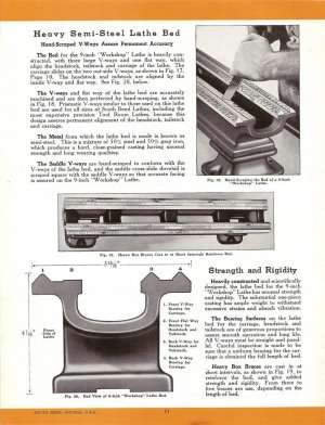
In starting out on some measurements to get some real knowledge of the condition of the 9A lathe, I searched hard to find out what the measurements are supposed to be. I found a single page in a thread on "Practical Machinist". I have attached the picture. It is useful for only 2 dimensions, and not-so-useful as a template to get up the sort of sketch I need. The picture was "rotated a bit"or "artistic", took liberties in the illustration such that the ways are not at the same level, nor the planed gaps between the ways, and I am pretty sure that on the real thing, they are!

I made my own sketch, with places to fill in the dimensions as either I measure them, or folks contribute if they happen to know.
So far, I have this..
SB9-profile3.png
On the measurements I took for the flat 10 between the ways , and then for the gaps 8, and 17, I find that flat 10 corresponds to 21/32", and gaps 8 and17 seem to be 9/16".
I measured 5.93" inches for the total width using a caliper, which corresponds OK to an attempt at 5+15/16".

I plan to discover the condition - a set of measurements. After the style of someone who did this elsewhere for a different lathe, we can decide which surface can be used as unworn reference, and how to work our way to the rest. I would hope that surfaces 8, and 17 are unmolested, and can be used as an original reference. The rack gear surface 2 can measured up to the top of the V-ways 5 with a micrometer, to try and prove they are parallel. In theory, the tops of the ways are unworn, and therefore good to place a level across. The actual condition, to look at them, is not so great as to leave me feeling good about such logic.

If 2 proves parallel to 5, and 20 proves parallel to 23, then I may start to trust the tops of the ways a bit more.

Then I will decide what to do with it. If the wear is not much, then at the very least, it gets a cleanup, a paint job, new wicks, and maybe some minor stuff like a serpentine belt, and a on-off switch. The MT3 in the spindle needs a cleanup. I expect that is something done with extreme care!

I think I have reached the point where I should continue with a new subject thread. To quote the old bloke from a previous century (millennium even), "It is not even the beginning of the end. But it is, perhaps, the end of the beginning"!
 

Attachments

  • SB-9-inch-bed-section.jpg
    SB-9-inch-bed-section.jpg
    144.6 KB · Views: 14
Last edited:
My first question is, "Why"? What will you do with that information? What CAN you do with it? As for wear, the carriage and the tailstock wear IN to the vees (which is why you will get a ridge that your fingernail can detect). The outside of this wear is still a reference. Also, your flats numbered 5, 14 and 20 are in the same plane and ARE a reference point (especially for leveling the lathe). Just make sure that any dings in them are carefully stoned out.

One of your earlier posts indicated that you could not catch your fingernail on the wear on the front vee? Did you reassess this? As for wear, it does not translate 1 to 1 on anything that you turn, so 0.005" of wear doesn't cause 0.005" of "change" as you try to turn a bar.
Hi SLK100. It is partly out of ignorance as to how much is important, and me just feeling my way into this. What I do with the information is rely on guys like yourself to have me know it is nothing to worry about. Also, given the general absence of information that could be found to make a sketch, it might prove useful to some reader with lathe bed in some other condition.

Finding out there is perhaps only an insignificant 0.001" wear is not something I knew to start with, and I am not even sure of it yet. Other than to notice I could not catch my finger on anything, I don't really know. It is also partly because there are inconsistent "features". I worry because of the severity of the dings, the appalling abuse of the quill, and for all I know, maybe somebody stoned the ridges out. I did imagine that the width of the carriage would to some extent "average out" one end or the other encountering wear. I have not yet done a proper clean-up. These are my first checks. Of course, once I stripped it down this far, I fall prone to the familiar instinct of not wanting to put back any bits that are not the best I can reasonably make them.

The flats 5, 14, and 20 are actually not so "flat" to look at. The original crisp edges are not there any more, kinda "rounded" over, although I dare say the very tops might still be at or near the unworn state, and would do if I put a level across it. I had the thought that, while avoiding the screw holes, surfaces 8 and 17 might do as an unworn reference. The idea was to put an indicator mount magnetically on the saddle, and touch the indicator down onto (say) 17, then move the saddle along, watching to see if the saddle "lowers itself", and by how much. Using the tops of the vees for this might only be done by putting a parallel across them, and indicating to the top of that, while sliding the carriage along. If a few checks from the tops of the vees show they are parallel to any other unworn lines, then I will obviously use them, they being so convenient to place something across.

Basically I get mixed messages when checking it out. I reason that the machine might have had a relatively short but unhappy life - not long enough to accumulate much wear, but having a period of encountering the dings and bad stuff when used. I note it has been given a cursory paint job at some stage, in the light gray color, but without disassembly first. The paint brush marks went onto parts of the labels, over the South Bend logo. There are areas under near the rack gear that were "missed out", and other evidence on parts of the saddle and apron.

In all, I am feeling more heartened by what I am finding. With luck, the saddle, and all the bits it carries might also be OK for a straightforward re-assembly. I am thinking ahead to what might be done to clean up the MT#3 in the spindle without risking making things worse. The MT#2 in the quill could be worse, but only just about! It surprisingly still "grabs" a chuck taper in the non-abused remainder. I see an eBay price for a headstock with quill of unknown condition exceeds what I paid for the 9C! :)
Not a fair comparison - it was such a bargain!

Perhaps just carefully putting in a MT#3 reamer, and gently cleaning up the 9A spindle taper internal surface by just turning the reamer by hand might preserve alignment with low risk. I will likely eventually be checking all that with a test bar. I see one can get reasonable examples from eBay, imported from India. (Item No. 174007647140). There are even some that have MT#2 on one end, and MT#3 on the other. I have no idea how good these are, nor even if I really need them. I suspect these might be among the most basic "essential" items when putting together a lathe.

Thanks again for your reply - G
 
I don't remember your spindle being banged up. If it will hold a MT3 center, then don't worry about it. The spindles are usually harder that a whore's heart, so anything other than carbide is not going to fix it properly. You will probably have the best luck just using a stone to knock down the high parts. A HSS reamer might work, but will probably be destroyed in the process. Your tailstocks are NOT hardened, so you can use your reamer to clean them up.

Your ways are banged up where most lathes suffer this type of damage. Putting chucks on and off does this. Nothing like forty pounds of steel all of a sudden becoming loose while trying to remove it. This is why I made this way-protector-from-heavy-chucks accessory for my lathe.

DSCI2204.JPG

DSCI2205.JPG

As you can see, it is just a piece of plywood attached to a piece of pine that fits between the ways and protects them from falling chucks.

As for your ways, surfaces 8 and 17 are not precision surfaces, so don't use them as references. As for bed wear, here is a chart that explains the effect of the wear on your cut:
Bed Wear Chart.jpg

As you can see, bed wear isn't really a concern for most of what we do in our hobby. Now, if we should get a contract for parts for NASA, or the ESA, then we may need to start worrying!
 
SLK001: You are becoming my Florida Springs lifeline in this. Thanks so much for the pictures and info. I did see, on YouTube, a video where the guy made up a wooden arrangement, I think of two pieces of plywood spaced by 2" wood, the bottom cut to fit across the ways. He pushed it up to the chuck, and marked around the chuck with a Sharpie, and cut the circles out, so that he could slide it over the chuck. Then unscrew the chuck, then tie it on to the jig. His plywoods also featured a carry handle This was to ease the business of unscrewing the chuck off the spindle, and getting it away without dropping it. I think he may have had some quite heavy 4-jaw kit, and like all of us, was feeling his age! In the end, he found his marked out holes ended up a tad lower than convenient to exactly screw a chuck back on, but that would be easily adjusted.

Regarding the spindle. I just looked up it, and it looked yuk, but if it is hard as you say, then it might clean up with rags and solvent. The "yuk" looked (hopefully) oily. I will only know if it is the "rusty" sort when I get a better look. Right now, it is, of course, all still attached to the headstock, which is stashed in nearby along with all the other major bits. I will be taking it all apart, if only to change the wicks, and it is definitely getting a new paint job!

The good news here is that I have established that, despite their "roundness" look, the tops of the SB-9A vees are pretty much parallel to the planed surfaces underneath. I mean surfaces 2 measured up to 5, and 23 up to 20. If they go up and down, they do it together! The nominal distance was clearly 3/4" when it started out. I measured at 10 intervals along the bed. They have their ups and downs in the tenths of thousandths, but nothing looking serious. The "front" top vees measure is about 0.001 more than at the "back", but that is all the measurements for the whole length. However high or low, they seem to go up and down together. We are in the region where some of the values are real, and some may have a component related to my measuring skills. The micrometer reads to 0.0001 on a vernier thing on the stem, using a 25 count around the barrel, and it can be a tad confusing until you get used to it.

I also have reason to think that surfaces 8 and 17 are likewise parallel to the reference surfaces. Surfaces 3 and 22 have no excuse to be anything other than original.

Your chart shows that even 0.01" wear, which is enough to have some members decide to either repair or retire a lathe, is still no big deal for making most things they might attempt. Thanks for that!

We are now into some of the filthy grubby cleaning up stages. Wire brushes, powered and otherwise. Paint stripper(s) various. Experimental de-rusting things going on. I won't bore anyone with all that!

In passing, you should know that the work I do has both of those outfits you mention as customers at the end of the chain. Hopefully not for much longer. (I am trying to move on to a life with no more rat-race, and not afflicted by "meetingitus" several times a week)!
 
Back
Top