An interesting project that stretched my skills a bit. This was a combination of welding and machining. I've heard that called a weldment.
One of the things that didn't come with this lathe that is relatively critical is a drive crank for the tailstock. The tailstock on this thing is truly massive. Even with well oiled ways, it's all I can do to slide the thing along the ways. Doing that requires standing at tailstock end of the bed and throwing my considerable body weight into it. The lathe is designed to have a hand crank that engages with the carriage rack to allow some mechanical advantage to move the tailstock. You can see the four holes (two bolt holes and two locating pins) on the side of the tailstock in this picture. Note the size of the tailstock relative to the one gallon paint can.

The crank needs to go over the V-way for the carriage and over the leadscrew (which is not installed in the above picture). I wanted a somewhat cosmetically pleasing design.
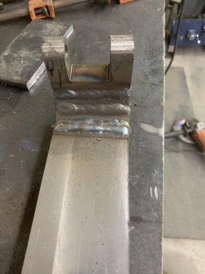
I started with some hot-rolled 1" x 3" bar stock, and face-milled off the mill scale. I cut four pieces. The first piece being a U-shaped piece with holes for a hinge pin, then two short pieces, and then a long tail piece. All four pieces had a 22.5* taper cut on the adjoining faces, and then those faces V'd out on both sides for weld beads. Welded that all up with the MIG welder.

Unfortunately despite my best efforts the hinge pin was a few degrees off from being 90* from the tail piece. I decided to taper the tail piece going down to give it a little more style, although it was really a fix for that problem. Ended up looking good so I'm pleased.
After a little work with an angle grinder, I had a decent looking piece.

Then I milled up the plate to go onto the tailstock, and the pivot block. The plate is faced 3/8" HRS, with a 1.5" x 1.5" x 2" block on the center. I had milled a 3/4" hole centered under the block, clamped it up and plug welded it to the block before welding the perimeter. I milled the weld off on the top. Here you can see the two together with the hinge pin partially installed.

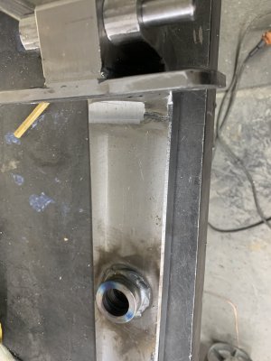
Next step was to make the through-hole for the shaft for the crank. Getting the location correct was a bit of a challenge. I fit the piece up onto the tailstock and used a 1-2-3 off the bottom of the rack to mark the location of the rack teeth, and then worked from there. Unfortunately I don't have a picture of that setup. But that gave me a location to drill for the shaft. I purchased a gear from McMaster, 8 DP 12 tooth 20* PA. Pricey, but I have yet to try gear cutting. My rotary table has way too much backlash in the worm, I'll need to work on that before using it for something like that. That gear has a 3/4" bore for a shaft. I started by drilling a 7/8" hole, and a 7/8" hole in a 1.50" diameter bushing to increase the contact area for the shaft. I also turned a 7/8" plug to drop through both to keep them in line while welding them together.

Once welded together, cut the piece to lenth around the hole using the horizontal bandsaw, then used the boring head on the mill to open the combined hole up to 1.0", giving me a perfectly concentric through hole. I then used the rotary table (no picture) to round off the bottom bandsaw cuts.

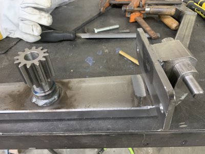
I turned a 1.001" OD, .753" ID bronze bushing, put the bushing in the freezer and the large piece in the shop toaster oven, and pressed them together for a good solid fit. Here's a test fit: This uses a scrap piece I turned for the gear shaft. Plan is to turn a longer shaft with a 7/8" hex end coupling protruding. That happens to also be the size of the carriage lock bolt on this lathe so I can use the crank to also lock the carriage.

Still need to make that shaft, and the handcrank, and then paint everything. Also waiting for some slight shorter 1/2" SHCS as the ones pictured above are too long to seat in the blind holes in the tailstock.


 Mike
Mike


