Lagunmatic CNC machine why not!

I connected a 3rd wire here, PIN4 going to Ground on JP11. Ground to common problem here?

I think you have it wired correctly

When the servo motor was making its noise it was applying voltage to both legs? At least thats what I measured on the bus bar.

There should be some voltage across the 2 legs of the motor. That's what is holding it in position. You would not measure to ground here, just across the motor leads. Bus bar? Not sure where you are measuring here.
 
Getting some where now! I partially took the X servo motor apart and looked at the encoder for some clues. Its a DataMetrics model 5-9872. A google search didnt provide any info. But .....The terminals on the encoder are labeled for # and function! worlds of info! lol The wires exciting them are also labeled which made a huge help. As o right now I have the encoders reading position in Kmotion on the axis screen. Turn the servo and the postion # changes. Feel like Im getting somewhere. lol

The encoder on the servo is labeled for AA BB and MM on the encoder. Doesnt say + or - but has a small dash line above one of the letters. Im currently using
1 5v+
2) common. ;)
3)A
4)B
5)M (z?)

Still leaves A B M with lines above them not being used.

This axis servo motor looks alot newer than the other two. I try and pull the baldor motors apart and see if I can get any clues from the encoders
 
Roger that.
Let me try and open the other servo motors to see if I can learn something from them.

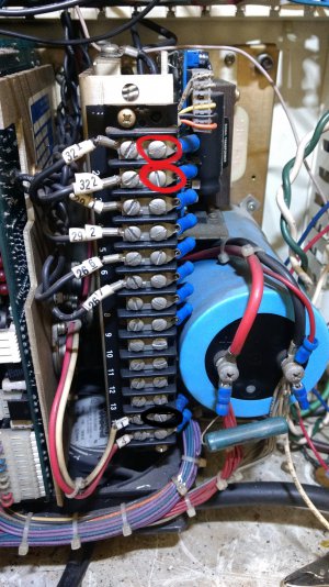
Heres a photo of where I was measuring for voltage. The #1labeled white is common all through the box. I have 6volts on 321 and 322 which go to the servos. Seems like I should have 0 volts when I turn the power button on?
Tested.jpg
 
All three servo motors have the same model of encoder. :)
What does the M stand for?
 
Heres a photo of where I was measuring for voltage. The #1labeled white is common all through the box. I have 6volts on 321 and 322 which go to the servos. Seems like I should have 0 volts when I turn the power button on?

That looks like a multi-voltage power supply. Not sure what the 321 and 322 do. What jumper and pins are they connected to on the drives?
 
321 and 322 go to the servo motor. All the black numbers go to the servo motors. They are connected to J5 on the servo drives. Looks like pin 7&8?

Ive got X and Y servo encoders talking to the computer. Y shouldnt be a problem.
 
321 and 322 go to the servo motor. All the black numbers go to the servo motors. They are connected to J5 on the servo drives. Looks like pin 7&8?

OK then those are the motor power wires. So checking to wire #1 won't tell you much since they aren't referenced to ground. You just measure between 321 and 322 to get the armature voltage.
 
Ah, gotcha.:drunk:
Should be 0 when I turn the machine on or should there be a little voltage to lock the motor? And the fans should come on? I feel like one of the relays is suppling power to something its not suppose to
 
Back
Top