-
Welcome back Guest! Did you know you can mentor other members here at H-M? If not, please check out our Relaunch of Hobby Machinist Mentoring Program!
You are using an out of date browser. It may not display this or other websites correctly.
You should upgrade or use an alternative browser.
You should upgrade or use an alternative browser.
JET 1240PD
- Thread starter WiscoF100
- Start date
Weldingrod is right. It's a micrometer adjustable carriage stop. Very handy.
The last owner may have been right about the VFD being marginal BUT it's a 3,000 watt VFD. A 3 HP motor draws ballpark 2250 watts so it might be enough. Settings are starting on page 11 of the manual at https://www.nvcnc.net/wp-content/uploads/2021/06/HuanYang-VFD-Manual.pdf which gives the factory default functions of the bus bar.
Does your forward/reverse/stop work through the spindle lever and brake pedal? If not and you would like some assistance, it's something I struggled through recently. I've set up 2 VFDs in the past 4 months. One, from a US company, went very easy. The other was an import that came with the lathe when I bought it and I had a lot of trouble with the instructions. If you would like some programming suggestions I'm happy to post them.
- Joined
- Jan 2, 2019
- Messages
- 7,160
Look up Mark Jacob’s on here @mksj
I don’t think he’s still building VFD systems but reading his posts will give you an idea of what’s involved in doing it right. If your VFD is just hooked up where a 3 phase plug or wiring would be it’s not going to really function properly. They should only be hooked directly to the motor with low voltage control circuits for controls.
If that’s the case you could use a static or rotary phase converter for full functionality of your machine as long as the original wiring is intact. Post a couple of pictures of the control box and how the VFD is hooked up.
John
- Joined
- Mar 30, 2024
- Messages
- 23
Awesome, thanks for the offers to help. Some good info to jumpstart me in the right direction.
The spindle lever works properly but iirc during the demo the foot pedal caused some odd behavior and his explanation was the way he had it wired or programmed. He offered to configure it but it was 19*, windy and the clock was burning fast. He mentioned using the vfd for deceleration of his liking but my memory could be completely wrong.
Seems I’ll need to move it away from the wall and verify the circuitry myself before I level it.
These pictures are of very little value
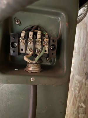
Junction from the cord
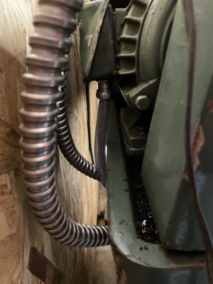
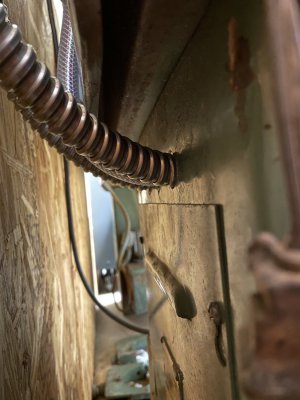
The two leads of conduit from the vfd go inside the cabinet and check out the custom braided vinyl hose protecting the motor circuit
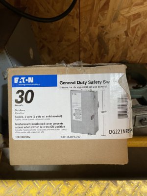
Might as well share my plans to electrify. 30a breaker, 34’ run of 10/2 and this 30a frn-r fused disconnect switch at the machine.
The spindle lever works properly but iirc during the demo the foot pedal caused some odd behavior and his explanation was the way he had it wired or programmed. He offered to configure it but it was 19*, windy and the clock was burning fast. He mentioned using the vfd for deceleration of his liking but my memory could be completely wrong.
Seems I’ll need to move it away from the wall and verify the circuitry myself before I level it.
These pictures are of very little value
Junction from the cord

The two leads of conduit from the vfd go inside the cabinet and check out the custom braided vinyl hose protecting the motor circuit


Might as well share my plans to electrify. 30a breaker, 34’ run of 10/2 and this 30a frn-r fused disconnect switch at the machine.

- Joined
- Feb 2, 2013
- Messages
- 3,963
The motor connection is wrong
Only 2 poles are getting power
Don’t operate until this condition is resolved, otherwise you may get smoke escaping
Only 2 poles are getting power
Don’t operate until this condition is resolved, otherwise you may get smoke escaping
- Joined
- Feb 2, 2013
- Messages
- 3,963
You’re going to need 4 wires for the motor
Given that the spindle control is working correctly and the foot brake caused some odd behavior, these are the things I would look at.
PD004: Base Frequency - This is your line current frequency; verify that it is set at 60.00 (60 cycles) since you're in North America.
PD007: Minimum Frequency - Your choice. I set mine to 30.00 so I could slow the motor down but not so slow as to overload it.
PD005 - Maximum Operating Frequency - Again, your choice. I set mine to 90.00 for some up speed control but not too much. Useful as you decrease the diameter of a facing cut and similar operations.
PD014: Accel Time - This creates a soft start for the motor. It doesn't need to be a long startup time; 1 or 2 seconds is enough of a ramp-up to prevent a big sudden draw on your household power. I set both my mill and lathe to spin up in 1 second and really like it that way.
PD026: Stopping Mode - Set to 1, coast to stop. This will let the brake work correctly. You don't want a timed decel mode when you use the foot brake. If this is not set correctly the spindle will continue to run even though the brake is engaged.
Ulma Doctor is right. That appears to not be a correct connection. Where does the black cord come from/go to? It looks like the line input from your 240V service directly to the lathe's motor. Where do the S and T wires go?Awesome, thanks for the offers to help. Some good info to jumpstart me in the right direction.
The spindle lever works properly but iirc during the demo the foot pedal caused some odd behavior and his explanation was the way he had it wired or programmed. He offered to configure it but it was 19*, windy and the clock was burning fast. He mentioned using the vfd for deceleration of his liking but my memory could be completely wrong.
Seems I’ll need to move it away from the wall and verify the circuitry myself before I level it.
These pictures are of very little value
Junction from the cord
View attachment 487839
The two leads of conduit from the vfd go inside the cabinet and check out the custom braided vinyl hose protecting the motor circuit
Might as well share my plans to electrify. 30a breaker, 34’ run of 10/2 and this 30a frn-r fused disconnect switch at the machine.
- Joined
- Mar 30, 2024
- Messages
- 23
The black cord is the line input. Idk what goes on inside the machine cabinet or the gray cabinet.
I can use all the spoon feeding I can get. I’ll move it and get inside to verify the circuitry in the coming weeks. I don’t just glance at a schematic and say right it’s suppose to be xyz duh. I have to see it physically and have lamens explanation to understand it.
Regarding PD026:stopping mode, rings a bell with what was going on. Like it wanted to drive through or had conflict with the brake. He said he used the vfd to decel. I assume since the machine was on a pedestal because the owner was very tall, he simply wouldn’t be able to reach the foot pedal on a 24” base!
Here’s a better shot from behind when I offloaded it
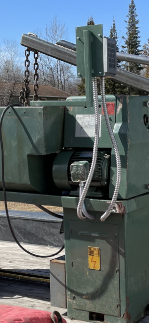

OK, what should be going on (and probably is, but should be verified) is the line input goes to the R, S and T terminals of the VFD. Your VFD can take either single phase or three phase inputs. Any two of the three R/S/T can be used for a single phase input so R isn't used. That's on the bottom of page 10 of the manual. Your photo shows the white to S and the black to T so just make sure that S and T go to S and T on the VFD.
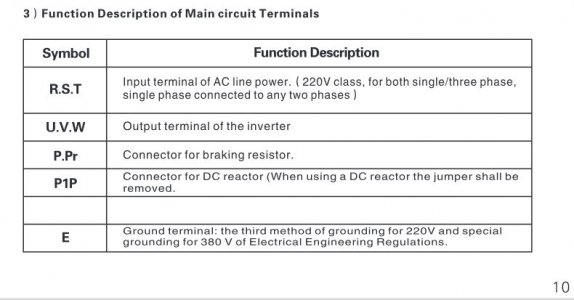
The green wire is ground. U, V and W on the VFD go to the motor. The green/white ground wire should go to terminal E. If it were mine, I would make sure the ground went to the lathe's casting as well.
It looks like you have identified the brake problem. The manual will walk you through making the necessary parameter changes.
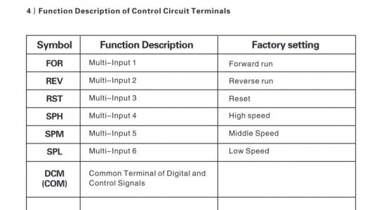
SPH, SPM and SPL are speed control presets for use with a switch to control speeds, as would be used in a conveyor belt operation so you can repurpose one of those terminals for the brake. For this discussion let's pick the SPL terminal to use for the brake. One wire from the brake's microswitch goes to the SPL connection of the Mini Inverter Terminals and the other wire goes to COM. These wires can be small as they only carry a low voltage. low current signal and the COM is getting crowded at this point. A 22 gauge wire is plenty heavy.

Once the wires are connected to the VFD a parameter has to be assigned to the SPL terminal. (Section 4. Page 11 describes the default terminal functions.) Setting the parameters begins on page 15 and gives step by step instructions on making a change.
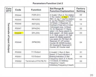
The chart at the bottom of page 20 addresses the parameters for reassigning a terminal. The parameter code for SPL is PD048. To set it to stop the motor set it to function 4: Stop. That should kill power to the motor but the VFD will remain powered up.
On my mill I purchased the VFD from Automation Direct and the instructions were very easy to follow. Setup was a breeze. I really struggled with this setup on my ENC brand VFD that came with the lathe because the manual was not as clearly written as yours. My brake initially behaved much like yours because it was never connected or configured.

The green wire is ground. U, V and W on the VFD go to the motor. The green/white ground wire should go to terminal E. If it were mine, I would make sure the ground went to the lathe's casting as well.
It looks like you have identified the brake problem. The manual will walk you through making the necessary parameter changes.
SPH, SPM and SPL are speed control presets for use with a switch to control speeds, as would be used in a conveyor belt operation so you can repurpose one of those terminals for the brake. For this discussion let's pick the SPL terminal to use for the brake. One wire from the brake's microswitch goes to the SPL connection of the Mini Inverter Terminals and the other wire goes to COM. These wires can be small as they only carry a low voltage. low current signal and the COM is getting crowded at this point. A 22 gauge wire is plenty heavy.

Once the wires are connected to the VFD a parameter has to be assigned to the SPL terminal. (Section 4. Page 11 describes the default terminal functions.) Setting the parameters begins on page 15 and gives step by step instructions on making a change.

The chart at the bottom of page 20 addresses the parameters for reassigning a terminal. The parameter code for SPL is PD048. To set it to stop the motor set it to function 4: Stop. That should kill power to the motor but the VFD will remain powered up.

On my mill I purchased the VFD from Automation Direct and the instructions were very easy to follow. Setup was a breeze. I really struggled with this setup on my ENC brand VFD that came with the lathe because the manual was not as clearly written as yours. My brake initially behaved much like yours because it was never connected or configured.
