
-
Welcome back Guest! Did you know you can mentor other members here at H-M? If not, please check out our Relaunch of Hobby Machinist Mentoring Program!
You are using an out of date browser. It may not display this or other websites correctly.
You should upgrade or use an alternative browser.
You should upgrade or use an alternative browser.
I am new here and need help with using a mini Lathe
- Thread starter EddieT
- Start date
- Joined
- Mar 12, 2022
- Messages
- 236
I have a similar 7x lathe. For online resources, some good ones have been mentioned already (MrPete, Blondihacks). A teacher I've found very useful is Marc L'Ecuyer' "That Lazy Machinist". Many good videos; it's like taking a college course in beginning machining.
https://www.thatlazymachinist.com/
If you use Facebook, the 7x mini lathe group has many helpful people.
https://www.thatlazymachinist.com/
If you use Facebook, the 7x mini lathe group has many helpful people.
Ive been learning from YT and dont have much machining experience.
That can be a double edged sword when you're learning new stuff. There are a lot of channels, a lot of folks sharing their work, and some of them doing amazing things.
Don't let the "pace" of a project on Youtube fool you.
Things that look simple often involve some underlying technique, that especially on the more professional/ex professional channels, and they often let the underlying technique slip by unexplained.
Sometimes a finished part with ten operations done to it, that comes out perfect, isn't the same piece you saw them start with.
You can and should get what you can out of Youtube, but BE CAREFUL, as you (almost) have to know what you're doing in order to sort out the good from the poor.
You have some good recommendations for some good channels.
I'm gonna second (third? Fifth?) the recommendation for "That Lazy Machinist" (start at the beginning), Blondi Hacks, (most all have something in the way of tips and hints), And mrpete222, (another to start at the beginning).
I have no real goal as such, but eventually i would like to make simple components.
Here is what i have been doing, just so we have an example.
I have some aluminium bar, which is 40mm diameter.
I used a band saw and cut a 60mm length, as i felt this could be chucked up safely.
I faced each end and also used the tailstock to centre drill and then drill out a hole in one end.
(not sure if my order of operations is right)
That sounds about right.
I found that the bar is nothing like a straight piece (which i understand) and when in motion that was very obvious.
I wasn't there, so I'm speculating, but here's something that I expect is going on.
1, lathe chucks (especially 3 jaw chucks, are not perfect. There is some technique to get a theoretically perfectly cylindrical piece to clamp straight in the jaws. If you cut the piece with a band saw, the ends were not square. (Really darned close maybe, but not square. Pushing that against the chuck face can influence how "straight" the part is when the jaws clamp it. Then when you face the opposite end, it takes that "split angle", where the part clamped down somewhere in between "straight" in the jaws, and "flat" against the chuck. And the new facing gets crooked. So you flip the part, and register it again against a crooked face....
Not to say that raw material is perfect. It isn't. But if you've got to duck every time it comes around there's probably more going on.
So I have used the lathe to turn it down and it is now 37mm diameter (which seemed a lot to remove - but i might be wrong)
Was that one cut? I'm guessing that's a very doable amount in "easy materials", it really depends on your lathe, your tools, and your materials. I'd venture to guess that you're into the "roughing cut" territory on your lathe (I might be wrong though). I think your finish cuts would probably be smaller than that.
And while you're reducing diameters... Make sure you KNOW if your cross slide dial reads tool movement (like any other tool in the shop, indicating the depth of cut, in which case it reads RADIUS reduction), or if it's a "diameter dial" that doubles the tool movement, so when it reads 1mm for example, the tool actually moves 0.5mm, and the DIAMETER is reduced by indicated amount. Either works fine, but you must KNOW which you have.
Currently my goal is that i need to learn how to turn both ends of the stock so the piece has the same diameter along the full length of the stock,
Not overly impotant what that number is atm, but lets same im aiming for 36mm along the length of the piece...
That's a tall order, and it's really going to end up being determined by the TOLERANCE in your parts. You can trun anything without a care , run over it with a file, and it'll look the part. If the actual dimension is both tight tolerance and critical to the application, you might find yourself turning between centers. Collets (All of them, and the chuck to hold them....) can help with that, keep the error real low, so faking it with a file can make a far tighter toleranced part. I wouldn't run out and get those just yet, as there are nine thousand kinds of collets and each kind has it's own size ranges and basically, you really need to know what you do the most before you jump off of that cliff.
As it stands, i have a ridge in the material at the moment. Its marginal but i can feel it.
A defect in a part will usually offer you a clue as to what's going on.
If that ridge is equal, all the way around the part, it's probably a depth of cut/repeatability problem with the lathe or the operator.
If that ridge is split so that it's "opposite" on opposite sides of the diameter, it's a problem with runout/repeatability in how it was clamped in the chuck, which may be a chuck problem or an operator problem.
If the "high side" of the ridge is ALL on the same side of the part, all the way around, but the size of the step varies, you've got both of those problems going on.
I think my speed and feed is 'ok' as the finish seems alright on the face and along the length of the aluminium, again i welcome any input and again, as i really am a novice.... please feel free to berate me or offer advice that you might consider way to obvious to mention!
Take that exact same bar, and do the exact same thing again. (Or a new chunk, or whatever). Stick it in the chuck, and measure the runout. Preferably with a dial indicator clamped, screwed, or "magneted" onto the cross slide or carriage, so you can measure the runout, AND traverse with the carriage to measure "crookedness".
Ideally (depending on tolerances, which parts of your parts are "working parts" with tight dimensions, and all that, precisely mounting a part would include-
Putting the part in the jaws as deep as you possibly can WITHOUT the crooked end touching the chuck face. As the part comes near to snug, you would rotate the part in the jaws as they're clamping. That helps it "find" the flat edge of the jaw that will hold it. Then you'd verify, with an indicator, that the piece is running true both at the chuck, and at the right end of the part. In practice, you're going to get a feel for how stuff goes in there, a feel for working with tolerances, and you're not going to spend all day mounting every single piece. But you'll want to play with that, and learn to read "shapes" on your dial indicator, as well as numbers. What does a "not round" piece of round bar look like when you rotate it under a dial indicator? What does a "round but off center" round bar look like. And again with moving the carriage (indicator attached). What does a straight but crookedly mounted part look like. What does a bananna shaped piece of bar part look like. This stuff will start to be very important if you want to ensure you get a part out of stock that's just barely big enough, or if you're repairing existing things, or you're making sub let parts for the space program, or whatever.
Starting out there WILL be successes, and there WILL be failures. You WILL scrap a part here and there. Save all of those. Pick numbers, and hit the new number, just to do it. Bore a hole in one to a dimension to make a press fit with the other one. Do dumb stuff that even an apprentice knows is bad form to see exacty what stuff looks like, feels like, and what the results are when you clamp wrong, cut too deep, cut too shallow. Cut some threads into stuff that is not to any dimension in the world, just to get the muscle memory down. Basically, just keep at it. Getting started can be a steep learning curve, and it never really ends, but it flattens out quickly after you get some of the basics.
- Joined
- Dec 23, 2012
- Messages
- 833
I found a few good thingsLots of videos, thanks for that! I shall deffo take a look
1 Good tool post like Aloris
2 Exstened cross slide travel
3 4 jaw chuck a little large than 3 jaw for odd work or large size
4 temperature gauge motor { low speed work the motor can over heat.}

Attachments
Last edited:
- Joined
- Mar 12, 2022
- Messages
- 236
Jake- You gave lots of excellent advice.
EDIT: Ignore these comments of mine. I assumed the OP had a 7x lathe, but he doesn't. A quick search seems to show it's an 8x with a 1100W brushless motor.
I don't think many 7x lathes can manage a 1.5mm (.060") DOC, even in aluminum; I wouldn't try it with mine, even with a good motor and a sharp tool. All the 7x lathe cross slide and compound dials indicate tool movement, as far as I know. But- as you imply- a session of 'cut and measure, cut some more' can teach a lot about the machine. Dealing with backlash, which involves some 'feel', is something that took a bit of hands-on experience for me.Was that one cut? I'm guessing that's a very doable amount in "easy materials", it really depends on your lathe, your tools, and your materials.
EDIT: Ignore these comments of mine. I assumed the OP had a 7x lathe, but he doesn't. A quick search seems to show it's an 8x with a 1100W brushless motor.
And while you're reducing diameters... Make sure you KNOW if your cross slide dial reads tool movement (like any other tool in the shop, indicating the depth of cut, in which case it reads RADIUS reduction),....... Either works fine, but you must KNOW which you have.
Last edited:
- Joined
- Sep 1, 2023
- Messages
- 1,229
I've done easily that much in brass. I have an Amadeal 714B which has less rigidity than the lathe that the OP has.I don't think many 7x lathes can manage a 1.5mm (.060") DOC, even in aluminum; I wouldn't try it with mine, even with a good motor and a sharp tool.
Obviously some grades of aluminium are grabby and gluey, copper too, but I think if you're struggling to get 60 thou cuts in softer materials, it might be worth taking a look at your lathe setup as far as leaving any rigidity on the tee.
ArcEuroTrade have some really good pictorial guides in PDF for 7x lathes that will apply to most versions of 7xs.
- Joined
- Mar 12, 2022
- Messages
- 236
It's likely not rigidity but lack of nerve on my part. The plastic gears in the Hi-Lo transmission start protesting when the loads get too high. anyway, my 7x14 Sieg is quite different from the 8x machines you folks are using. My comments don't apply; I don't know why I assumed the OP had a 7x lathe.I think if you're struggling to get 60 thou cuts in softer materials, it might be worth taking a look at your lathe setup as far as leaving any rigidity on the tee.
- Joined
- Sep 1, 2023
- Messages
- 1,229
Mine's a 7x too. It's this, but with Amadeal branding (Amadeal have a different model called 714B now):It's likely not rigidity but lack of nerve on my part. The plastic gears in the Hi-Lo transmission start protesting when the loads get too high. anyway, my 7x14 Sieg is quite different from the 8x machines you folks are using. My comments don't apply; I don't know why I assumed the OP had a 7x lathe.

To be fair, it's got the brushless 750W motor and I have been working on it to improve its rigidity, but I haven't yet fitted the central shear plate (got the idea from Steve Jordan's YouTube videos) as I'm not yet finished lapping the underside of the ways in the middle.
@VicHobbyGuy Just re-read your post properly and now correctly understand you were taking about the gears on the spindle inside the head-stock (the Chinese mini-lathe's implementation of a back-gear), not the changewheel gearing; apologies for my lazy reading comprehension failure!

Mine's a brushless motor model so the headstock as sold didn't have the hi-low gearing. However, after an unfortunate accident with a hydraulic press whilst changing out the deep-groove ball bearings for angular contact bearings, I now have a replacement headstock with the hi-lo gearing. Initially I just rebuilt the headstock assembly without that gearing and used my lathe for a while. Now I'm in the process of further modification/fettling, I'm going to put the layshaft and gears back in and hopefully enjoy the improvement in torque at lower speeds that it should provide.
The spindle speed display will now only be a motor RPM display, mind you, so I've had to buy a castellated disc and a new tachometer sensor and display. I'm thinking about a new lathe controls layout (moving the hi/lo gear lever to the front) so I might keep both displays. Maybe the motor RPM will be useful information; I dunno.
Anyway, after all that ramble, I should mention that my hi/lo gearing is some kind of metal (a hardened steel of so.e kind, I'd hope), so I expect the lathe to be a bit noisier but eh...I don't mind if my machine partners in the business of making scrap from perfectly good stock have a bit of a shout at me. Like you say, it can give one a bit of an early warning that one is taking the **** and needs to.back off a bit.

Last edited:
- Joined
- Dec 18, 2022
- Messages
- 2,740
I would install your others set of jaws, they will hold your work better.Sorry i didn't intend to be vague.
I am starting out so i've only a few hours of use of the machine to try to learn basic stuff like facing, turning drilling etc on the machine.
Ive been learning from YT and dont have much machining experience.
I have no real goal as such, but eventually i would like to make simple components.
Here is what i have been doing, just so we have an example.
I have some aluminium bar, which is 40mm diameter.
I used a band saw and cut a 60mm length, as i felt this could be chucked up safely.
I faced each end and also used the tailstock to centre drill and then drill out a hole in one end.
(not sure if my order of operations is right)
I found that the bar is nothing like a straight piece (which i understand) and when in motion that was very obvious.
So I have used the lathe to turn it down and it is now 37mm diameter (which seemed a lot to remove - but i might be wrong)
Currently my goal is that i need to learn how to turn both ends of the stock so the piece has the same diameter along the full length of the stock,
Not overly impotant what that number is atm, but lets same im aiming for 36mm along the length of the piece...
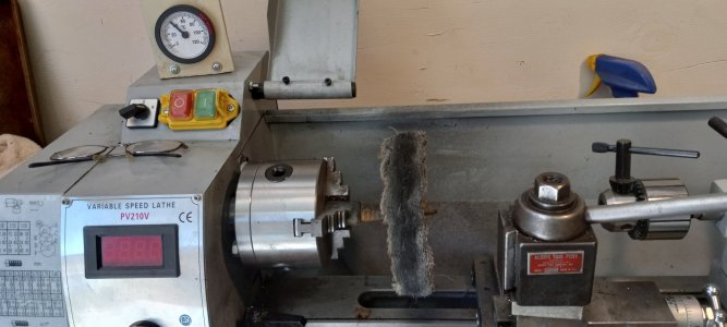
As it stands, i have a ridge in the material at the moment. Its marginal but i can feel it.
I think my speed and feed is 'ok' as the finish seems alright on the face and along the length of the aluminium, again i welcome any input and again, as i really am a novice.... please feel free to berate me or offer advice that you might consider way to obvious to mention!
So what i am asking is how do i go about that, super dumb i know but whats the advice on how to do that and what equipment should i be using to assist me.
(a couple of pics attached in case they help in any way - you can see the ridge line where i turned on side, then rotated the piece and tried the other end)
like a said newbie, go easy on me")
Jake- You gave lots of excellent advice.
I don't think many 7x lathes can manage a 1.5mm (.060") DOC, even in aluminum; I wouldn't try it with mine, even with a good motor and a sharp tool. All the 7x lathe cross slide and compound dials indicate tool movement, as far as I know. But- as you imply- a session of 'cut and measure, cut some more' can teach a lot about the machine. Dealing with backlash, which involves some 'feel', is something that took a bit of hands-on experience for me.
EDIT: Ignore these comments of mine. I assumed the OP had a 7x lathe, but he doesn't. A quick search seems to show it's an 8x with a 1100W brushless motor.
I saw the model number as something something 210 and took it too be an 8X lathe. Not night and day, but certainly a step up. But now I see that this company's 7X is numbered as something something 714, so now I question whether I was right in assuming 210 meant millimeters....
I got the right answer apparently, apparently based on unwarranted assumptions....
Lesson- Don't ever take anything some stranger says on the internet as being written in stone.
Similar threads
- Replies
- 11
- Views
- 571
- Replies
- 12
- Views
- 663
- Replies
- 8
- Views
- 589
- Replies
- 2
- Views
- 185
- Replies
- 19
- Views
- 1K