Group Project: Dividing Head - Organization and Design

The indexing plate as Mark did it would not hold the weight of a chuck. It was just for indexing, he had the nose of the spindle threaded to match his lathe chuck.

BUT it might be possible for me to design the indexing plate to be strong enough to mount a chuck to.
Isn't an indexing plate just a plate with a bunch of holes in it that a pin goes through? I don't really see a reason that couldn't just be a blank backing plate with a bunch of extra holes in it :)

If we're doing something like that, I can volunteer for it. Largeish rounds are cheap enough to buy, and my lathe takes material quickly, so getting them to shape isn't a problem.

The indexing holes are of course a pain, but the DRO + a stubby length drill (Removes the need for a center drill) could likely get me done with not much time investment.
 
The indexing plate is not normally mounted securely enough to support the weight and cutting loads of a chuck, it is just for locating the index points. But that does not mean that it could not be designed to carry those loads in this case.

I can do anything, the impossible just takes more time.
 
I personally am more direct into everyone making their own backplate for the specified part and leave the indexing plates normal like the B and S style
 
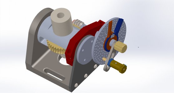
OK, Here is the first STP file.
Remember, DO NOT start making any parts or acquiring any material based on this file, there are parts floating in air and things that WILL be getting changed.
 

Attachments

Last edited:
A lot fewer parts floating in air.
Still DO NOT try to order material or make parts from these files.
I added a pic for those that do not have a CAD program to open the STEP file.

If you do see anything that may cause you issues with the parts you are making let me know so that I can work with you on it so that everyone will, or at least can be successful.
 

Attachments

What did you decide about the worm ratio? I confess I don't understand how to choose this. I see rotary tables using a 90:1 worm which is 4 deg per turn. That makes no sense to me? With a 72:1 worm you would have 5 deg per rotation which seems more useful. What am I missing about the 90:1 that would make it desirable?
Robert
 
For me i am not sure what type of attachment i will be using on the business end. I have a South Bend 9A but idk what threads the spindle is. I know i plan to get some 5c collets at some point so if that was possible to set up to hold them that would be great. Or like we once talked about leaving the spindle open for the owner to change how they want? A neat concept would be if you can set up the spindle to be interchanged in a way so you can go from 5c to a lathe chuck. Although if we set the spindle up to hold a lathe chuck with threads or which ever, i can always make my own adapter to hold 5c.

Your 9A spindle has 1.5X8 TPI threads.


Sent from my iPhone using Tapatalk
 
What did you decide about the worm ratio? I confess I don't understand how to choose this. I see rotary tables using a 90:1 worm which is 4 deg per turn. That makes no sense to me? With a 72:1 worm you would have 5 deg per rotation which seems more useful. What am I missing about the 90:1 that would make it desirable?
Robert

We're using 40:1. Nine degrees per turn. The worm is going to be a short piece of acme threaded rod, which results in an approximately 3" gear.
 
We're using 40:1. Nine degrees per turn. The worm is going to be a short piece of acme threaded rod, which results in an approximately 3" gear.
Won't 9 deg per turn be cumbersome? For commonly used positioning like hexagons or octagons you will have non-integer handle rotations. I have a 4" rotab that is 72:1. I am not trying to sound critical, I just want to understand this better especially before I buy a 6" table. I guess for gear making with a dividing head you might not care about the integer synchronization? That is what the index plate is for?
Thanks
Robert
 
Back
Top