Going To Buy A Lathe... Thoughts, Input Solicited By Inexperienced Dufus

Mark,

I think those ways are in a tad better shape from the pictures above than what we spoke of over the phone this morning.

Ken
Well, I'll take that...LOL Good news is good news. This goes back to what Splat said on page one of this thread: I'm a newb. How well can I judge it? You were relying on my eyes. I was trying to be accurate.

Anyways, so still a good choice, I hope.

Thanks!
 
Congrats on your new lathe!

Best to see how well it holds a tolerance once you get it running, then decide what , if anything, to do about those ways.

I had a similar ridge near the headstock resulting in .003 of taper over 2", which could be compensated for, but was still a PITA. What I ended up doing was planing the bed myself
using the unworn tailstock ways as a datum. Building a planer jig from the tailstock base is relatively simple, but you will need a compound or cross slide to duplicate the angle of the v way.
If you are interested I can give more details later. I thing 4gsr built one of these for a grinder, I found planing much easier.

There are other ways to work around that worn area:
1. Set up a steady rest and work further from the chuck end.
2. Build a chuck extension
3. Move the headstock down past the worn area.
4. With such a long bed you could even set up a second headstock further down the bed!

Yes, I figure I'll have to either learn to work around it or do something more "radical." I guess my priorities at this point are getting it home and then getting it running so I can see how bad it hurts me as it is.

That's a lot of lathe! Looks to be in pretty good shape.:encourage:

It's a whole lot of lathe. And then, for all my talk about the requirement for a taper attachment, I didn't even take pictures of this one, apparently. (Could have sworn I did.) It's a rather nice unit. I've been spending some time thinking about how I could make it movable in my shop. Problem is, once I hire lift to offload it, once it's there, it's there unless I come up with something first. Thoughts?
 
I've been spending some time thinking about how I could make it movable in my shop.

You could put it on wheels. I have a 5000 lb milling machine sitting out in my shop that is on castors, it actually moves pretty easy. You could do something similar. You would still want leveling screws for the lathe, but raise the screws and it would allow it to move around. I assume it wouldn't be moved often.

upload_2016-9-18_8-57-47.png
 
You could put it on wheels. I have a 5000 lb milling machine sitting out in my shop that is on castors, it actually moves pretty easy. You could do something similar. You would still want leveling screws for the lathe, but raise the screws and it would allow it to move around. I assume it wouldn't be moved often.

View attachment 136181
Jim, That's exactly what I was thinking. If I build a frame, say out of 4x4 square tube, put a collection of heavy duty casters on it, and also a collection of jack-screw feet, I could do that very thing. I think it wouldn't move often in the long run, but initially, as I'm getting my shop the way I want it, and as I work on the lathe itself, the ability to reposition it, pull it away from the wall to work behind it, and all of that would be indispensable and highly utilitarian. The only thing I worry about is height. On the other hand, I'm a tall fella, so that may not be too much of an issue. Playing with it yesterday, I felt like I'd be happier with the carriage wheel being about 6 inches higher anyway. I think the trick would be to build it so that a.) it's sturdy enough, b.) it's not constantly in the way, and c.) so it doesn't raise it up too much. I even thought about how if I used nested square tube, I could make the casters on the front side be mounted on removable outriggers so that once it's in place, and I've leveled it on its feet, I could pull the front caster outriggers and get them out of my way. If I needed to move it, slide 'em back in, lock 'em down, raise up the screw jacks, and away we go... Well, slowly of course... I might be over-engineering it, but here's a very, very rough, not-to-scale drawing:
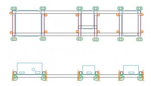
rough_dolly.jpg
Main rails are black, cross rails dark blue, removable outrigger beams red, casters green, jackscrews orange, pedestals of lathe in light blue. Again, not to scale, just spit-balling. Would probably extend main rails on ends enough to give my end jack screws two welded surfaces inside the corner. Again, just spit-balling. Advantage of under-slinging the main beams here is that I reduce the amount of raising I'm doing to the height of the casters, and not the casters PLUS the height of the beam. These casters would be 6" diameter, 1200lb each capacity, overall height of 7-1/2, so that's how much I'd be raising the lathe, plus whatever amount of leveling. As I said, I'd make the front side caster outriggers removable so that after leveling, I could pull them out and get them out of the way. The ones on the back side would stay, though again, there's be no weight on them unless I was moving it. Does this look feasible to you?

Thanks!

Edited to add: The only additional thing I might do here is break the main beams just to the right of the headstock pedestal, and nest them together, sort of like the outriggers for the front, the idea being that if I decided the bed was intolerably worn, and wanted to pull it all apart so I could take the bed to be ground, I could effectively slide the bed out, I think. I'll have to look more closely at how the bed is joined to the headstock/gearbox, etc, and see if that's even feasible...
 
Last edited:
Looks perfectly feasible to me. I like the idea of removable outriggers on the front side, you don't want to be tripping over them when operating.

I like the underslinging, lowers the CG, lathes are normally really top heavy.
 
Looks perfectly feasible to me. I like the idea of removable outriggers on the front side, you don't want to be tripping over them when operating.

I like the underslinging, lowers the CG, lathes are normally really top heavy.

Yeah, I just have to make sure my welding is up to snuff... Would be terrible to set the lathe on it and have the bottom fall out...LOL Of course, once in position, with leveling screws jacking it up, all the weight goes back on the main beams directly. So if I'm not being lazy and leaving the weight on the casters for an extended period, all the weight should remain on the main beams 99.9% of the time(any time it's not being moved.)
 
BTW, do you know a good source for jack-feet that won't set me back a mortgage payment per? And what diameter do you think I'll need with a dozen of them supporting the load here? Figuring the weight of my frame plus the weight of the lathe, 7500-8000 lbs?

Thanks Jim!

Mark
 
Back
Top