Inspection results:
I arrived about 10:02 this morning at the appointed place in Victoria, Texas. I met the gentleman selling the lathe, and he took me to the shop where it's currently sitting(where they'd brought it to see if it could be powered up and discovered some significant electrical problems. Basically, I'm going to have to rewire this beast, and probably replace the motor. At least I know what I'll be getting, and I knew the electrics would need work going in. More on that later. For now, let's talk about my findings on the mechanical inspection.
The lathe in question is a 1979 model Martin DLZ502. It was made in Germany. It's a newer version of the same lathe another poster here on H-M has acquired. He's been helping me a bit by providing me some pictures of his machine. He's been a big help, and has my extreme gratitude. So, a little about the characteristics of this lathe. It is a gap-bed lathe, theoretically 2000mm between centers (or around 79") It has 500mm(almost 20 inches) of swing over the bed. It weighs probably between 6500-7500 lbs(unfortunately, the data plate and name badge were missing, so I don't have a precise weight figure.) It theoretically cuts metric, imperial, module, and dp threads. It has a taper attachment and its spinfle bore is.... 4.25 inches(quick and dirty steel rule...didn't pull out calipers... This picture should permit you to see and get some idea of the scale of this beast.
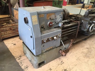
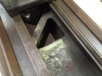
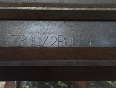
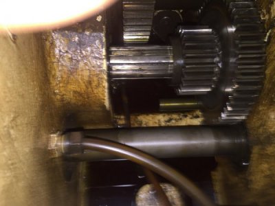
I decided apart from a beginning cursory walk-around, my next step would be to pull the lid off the gearbox. My think was that if it's junk in there, no point going on. I was 6'4" in youth(although I'm sure my spine has compressed some with age,) and the lid on the gearbox is at roughly base-of-breas tbone height for me. It's a good thing it wasn't taller. That cast lid weighs quite a bit. It would have to be around 90-100lbs. O pulled the 8 socket head screws that hold it in place. I had to be careful when sliding it off because there's a little sight gauge into which a small tube from the oil pump extends, I suppose to let you see that the pump is running, and there's oil in the gearbox being circulated. There's also a tray with a lip onto which that oil land and then, I believe, spreads and falls onto the shafts and gears. There are two small diameter tube that run from the pump to the spindle bearings to keep them happy. I did find a deficiency. It looked to be an ancient wound, but something the lathe has run with, probably for a long time: IF you look at the face of the gearbox, you'll note there's a longer handle that goes directly into the case(not the big dial-face spindle speed selector, but to the right of this.) If you look, you can see there is a small round red dot panel and a small round black dot panel, and these indicate the gear range. It translates into high and low range, effectively. So this shifts the machine between the speed ranges in black and red marked on the dial face. At the other end of the shaft operated by that handle is a pair of gears, one small, one large, and they mesh with a small and large gear each, (of course only one at a time) and that is controlled by this lever. Sometime in the history of this lathe, somebody attempted to shift this lever from low to high range without stopping the spindle first, and the edges of those two gears have some ground-off metal missing for about 60 degrees of a turn on the spindle gear and almost 3/4 of a turn on the mating gear, and only about 15% the width of the teeth on either. No other gears in the gearbox have any kind of damage I could detect. I inspected them all, visually, and by looking for sharp edges, missing chunks, and so forth. I couldn't see any damage or feel any damage anywhere else in the box apart from the two high range gears. After fooling around with it extensively, I don't think it will affect the lathe's operation. It had to have happened some time well in the past, because I couldn't find any grindings, chunks, or other gear metal in the gearbox, in the oil sump or anywhere else. The incident that caused the damage must have happened before its last oil change, and that would have been well before it ceased operation because the oil, while not "bad," certainly isn't new or fresh. Some newb like me grabbed a handful of lever while the spindle was still spinning at speed, is my best guess. It's a little ugly but I don't think it's a show-stopper. There's still about 80% of the width of the two gears that have no discernible damage, and as I said, I think it's been that way a long time, because it made no grinding, scraping, clacking noise once shifted over to high range. The low range gears have no such damage, so we know which way the newb had been shifting. Either somebody stopped him from trying to shift it back, or the collision slowed the spindle to abruptly with an awful racket and he wised up, refraining from forcing it further. So the pair of high range gears are a little ugly, but they seem to work, seem to mesh without difficulty, and it seems to have happened some time ago. All in all, the gearbox is in good shape with the deficiencies noted. It should work fine and last with proper lubrication AND operation.
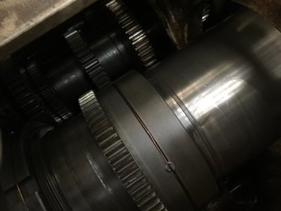
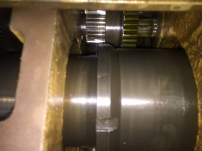
The gear on the right side here is the one with the most damage. Unfortunately, I didn't get a picture of the damaged segment. Had I turned it a further 1/4 turn or so before I took this picture, you'd see it. The gear to which it mates on the spindle is the other slightly damaged gear. The smaller gear here mates with the large gear at top left to give the lower speed range, and the one at right has a mate just out of the picture(currently engaged here). These two in slide back and forth on that shaft as the lever on the bulkhead is thrown.
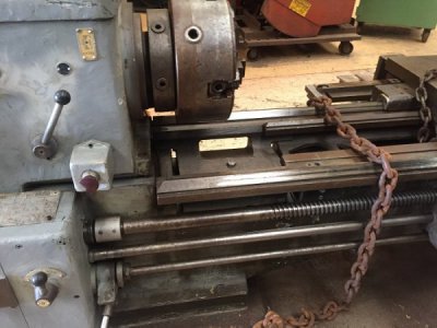
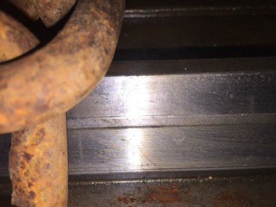
Next I moved on to an examination of the ways. This was the thing that turned out to be the debating point for me. There is significant wear on the ways at the head end. It's significant on both the back of the rear way and the front of the forward way. It's enough that there's an unworn ridge in the middle of the ways that it plainly visible from the first picture below. This ridge slowly disappears as you move tail-ward so that it seems to be a fairly uniform situation. It's not abnormal to have much more wear near the chuck end and much less at the tailstock end, from all the lathes I've looked at. Truth is, if not for the unworn ridge, you wouldn't otherwise realize how worn the ways are, because except for where the wear substantially begins in the gap-section of the bed, there's no "low spots". It's a long taper from the low spot in the gap section out toward the tail end. One of the wipers on the saddle has a broken mounting plate, with a broken-off screw, and the broken piece missing. I think I can drill and extract that screw and make a new plate without much trouble. The tailstock ways look fine, with the exception of at the extreme head end, where they have some gouges and chunks. Again, this is irrelevant because I don't imagine ever really using the tail stock way up there. Other than the gouges, from dropped metal items I'm certain, there's no wear at this end of the tailstock ways, so apparently, nobody else used it this far in either.
Front side of forward way.
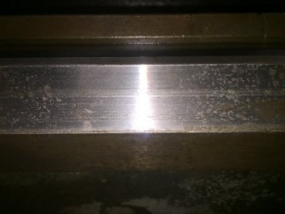
Rear side of back way.
Near the tailstock end:
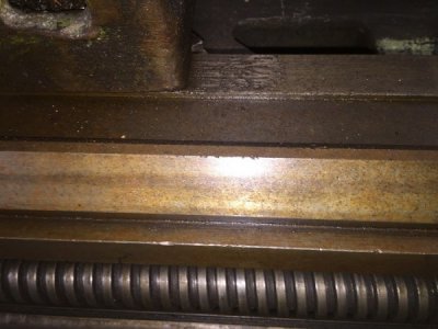
My biggest concern about the wear I see may be exaggerated by that perfectly straight, perfectly centered, unworn ridge that's about 3mm wide the whole length of the bed until you get to the tail-stock end. It's almost as if it's there for a reason, by virtue of a gap/slot in the saddle where no wear can occur. Could this be some kind of intentional wear indication? At it's worst spot, close to the headstock, it appears to be the thickness of about 2 sheets of paper, or a hair more.
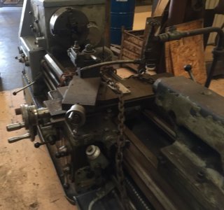
That tailstock is a massive sucker. I would guess it must weigh at least 350 lbs, maybe more. It's huge. Sorry, back on task.
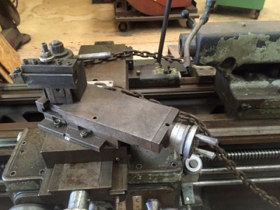
One of the things that happened during my inspection is that I received a call from one of our members, 4GSR, who lives in the vicinity, but was otherwise engaged, yet still made time to give me a call and coach me through some things. We'd been corresponding about this lathe, and he expressed an interest in helping me out, for which I am quite thankful. I had some questions about things I was seeing, and he helped me figure them out. While on the phone with him, I looked at what happens when one locks the carriage half-nut on the lead screw. Moving the handwheel, I found that it would travel (eyeballed, as I was holding the phone with the other hand) somewhere in the 1/32" to 1/16" despite being engaged on the lead screw. 4GSR suggested, and I'm in agreement, that the half-nut is probably worn. The threads on the leadscrew itself look pretty good, and while there's a wee bit more wear from the middle of the bed and in, it's not much. I think most of the wear is to be found in the half-nut. Weirdly, there may be a source for this half-nut, so maybe something I can tighten up. The cross-slide moved smoothly, and there was not a ton of lash in the feed crank. The compound had a half-turn of lash though, but 4GSR suggested that might be something simple, like the nut being loose or something. It seemed excessive, but probably something fixable.
The electrics need to be stripped out, to the degree they're there at all, and burned. Okay, maybe that's hyperbole, but let's just say that I'll have a time of it getting this running. There isn't much there. Probably needs a motor too. Of course, I knew that going in.
So decision time. I spoke with 4GSR at length about this because my worst concern is those ways. They're the thing that's going to throw off my accuracy and so on. Still, the degree of accuracy I need for most jobs here on the farm probably doesn't warrant the extent of my concern. Also, because I wound up negotiating a good price on the machine, and because I love fixing up old things, making them useful again, and because I need something that will leave me the money to buy tools with which I can actually use the machine, and with some reassurance from 4GSR that I could overcome most of these issues, and also reminding me that most of the things I'll make won't demand .001 accuracy(or anything real close to it) anyway, this machine should suffice as a learning platform, and to produce useful items for use here on the farm, and it's definitely in my price range, all things considered. I hemmed and hawed in my head for a bit, and then the seller showed back up and asked what I thought. I told him about the deficiencies I discovered, some known, some unknown to him, and I had to decide. I looked at the lathe, I thought about the work ahead of me, and said "Ah, what the Hell." "Sold!"
So I'm the proud owner of a pile of work. It'll be a couple weeks before I can go pick it up. The first thing I'll need is to clean the snot out of it. It's dirty, dirty, dirty. It's in need of much love. It's been repainted at least twice that I could tell from where paint is chipped off of it in spots. The original color is good old pale machine green. Here's an example spotted on google images:
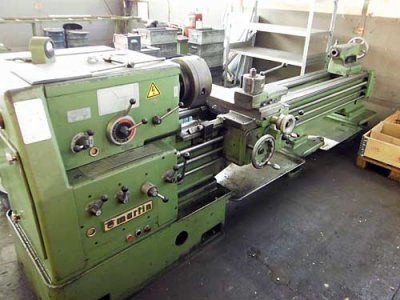
By the way, the image above is a '69 if memory serves. Though very similar, not exact.
Then it was painted with a kind of battleship/deck gray, as can be seen on the pedestal under the headstock. Then you notice the lighter gray, almost a primer gray, with which the headstock has been repainted. Time for a serious makeover. It's missing half the ball-knobs from handles, but I'm sure I can find them on ebay or even make them. The thread-table plate, and all the other plates around the machine are legible but filthy. (Except for the missing main data plate, which is, well, MISSING...LOL)
The steady rest is another big hunk of metal. I see a lot of work in my future.
Pickup is provisionally scheduled for the first Sunday in October, weather permitting.
Well, am I dead-bang nuts, or did I do "okay?" Apart from not running, I did get every feature on my shopping list. Oh, and there's something else a little interesting. There's an accessory socket that is mounted near the very bottom of the middle pedestal, in back:
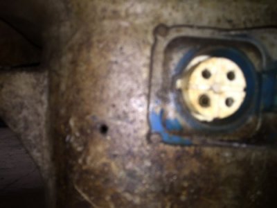
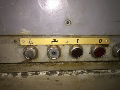
I suspect this is for light and coolant pump, though neither accessory is present. I believe this because two buttons on the front panel seem to correspond to this, one with a light icon, and the other with a faucet/spigot icon. I could see where in 1979, that would have been a nice touch:
In the end, here was my reasoning on the ways. Tell me if I'm thinking wrong here. This wear on the ways affects the height of the tool in relation to the piece of the turning stock material. This means that as I move the tool from left to right, the tool will rise very slightly on its path because the ways are no longer parallel to the centerline of the stock. The longer the piece, the worse the built-in taper, right? Good so far?
This means that if I were trying to, let's imagine, turn a piece of 1.25" bar-stock into a 1.125 turning, There would be variance because I would either start at the tangent formed by the tool and the stock, or above it, or below it. As I moved the tool leftward, this would move the line of the cutter downward in relation to the centerline of the stock. The result would be a taper. If I started right at the tangent relation ship, my turning at its chuck end would be larger than the intended diameter because as we moved the tool left, it moved downward and no longer at a tangent to the stock, the turning would get progressively wider(I'd be removing less and less material.) If I started slightly above a tangent, my turning would get narrower as I moved from right to left, but once past the tangent(now below the centerline of the stock), it would begin to get wider and wider again. Am I tracking correctly? If this is the case, then, if I really, really, really needed something more precise, couldn't I make the first pass at the tangent, and then adjust the tool up in small increments and make repeated passes until while starting above the tangent line, I was now finishing right at it? Wouldn't this make my resulting turning the same diameter, end to end? Now, I also realize that the longer the piece, the more adjustments in tool height and passes I'd need to make, and this would get ridiculous, because there are infinite points on the line, so an infinite number of adjustments/passes would be required, but only to make it "perfect." To get it within .001" wouldn't require infinite passes, but definitely many more than two or three over say a 12" run. I'd have to work the geometry a bit more formally to figure out the number, but that calculation seems to be within the realm of feasibility.
Now I could see where this approach and external threading of stock would not work so well, but I could also then chase my thread with a hand tool, so maybe not so big a deal?
Okay, that's probably enough "outside-the-box" thinking. All my life, I've had to work with imperfect tools, and still gotten decent results, in part because I've always accepted my Dad's and Grand-dads' admonition: Only a poor musician blames his instrument.
Thanks all. Oh, and btw, now there are two Martin owners here. How many does it take to get your own manufacturer forum?
JUST KIDDING!
Thanks!
Mark

 Don't worry about the electrical, we can start from scratch if needed. Pictures of what's there would be helpful after you get it home. Don't need them right now.


