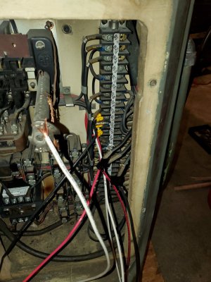
Cincinnati Toolmaster 1-A

Did you totally isolate the connections from the upstream wiring in the machine?
Leg *T2 is a common bus. It may be crossing between the two VFDs.
 
Did you totally isolate the connections from the upstream wiring in the machine?
Leg *T2 is a common bus. It may be crossing between the two VFDs.
The upstream wiring meaning all the stuff on the D1/2/3 side of the tall column the motors connect to? Yes I believe so, the first Teco VFD is connected on the TxA side of the column, i.e. not interacting with the column at all, it's just VFD straight to motor (or rather drum switch and then motor). The second VFD is wired through the D1-2-3 D/E side, not directly through the motors but through that column. However, no lines from the other circuitry go to any of D1D, D2D, D3D, D1E, D2E, D3E, as I disconnected those and left them hanging. I'll tape up the loose connections and try again in case they occasionally accidentally make contact with the column.

Still, it seems odd that it's a relation between the spindle motor and the cross feed motors, when the spindle motor's only connection to the rest is through the VFDs sharing the same 220V input line.
 
You might power up the spindle and see if any stray electrons ( i e voltage) shows up on the legs feeding the table.

How is the system grounded? I had issues with the ground playing up my DRO.
 
You might power up the spindle and see if any stray electrons ( i e voltage) shows up on the legs feeding the table.

How is the system grounded? I had issues with the ground playing up my DRO.
I think this weekend or next I'll have to do that and otherwise dig through all the electronics with a voltmeter.

I'm on a 3-prong 220V plug so the "ground" (neutral) goes to the first VFD's body (the specified grounding location), then to the second VFD's ground terminal and then out to the mill's control board to all the motors' neutrals.
 
Two things come to mind. First off, I am not a fan of using the neutral for ground. Yes, I know they grandfathered in old 3-prong drier plugs. I don't agree with it. Second, do not daisy chain grounds. Bring each back to a common point. VFD1 to plug. VFD2 to plug, machine frame to plug. I originally had mine wired with the ground (real ground) to the VFD, then passing on to the machine frame. My DRO kept picking up noise and the X axis would wander on it's own. Changing the ground to a star rather than daisy chained fixed the DRO issue, and I assume others that weren't noticed.
 
Well something wasn't right. I had the grounds in a star (as well as the hots and neutrals, separately), plugged it in and had both VFDs light up as usual, turned on the spindle motor to cut a lathe QCTP base and then the Chinese VFD which hadn't been turned on (I gave up on that after not being able to figure out why they both couldn't be turned on at the same time) popped like a glass bottle and went up in smoke. The Teco VFD didn't pop but went dark so might be toast too, I'll have to check when my blood pressure comes down tomorrow.

Before all that, I had been getting stray voltage readings on the legs of the Chinese VFD even when it wasn't turned on. I was even getting voltage readings just in the air near the Chinese VFD. So I'm assuming it's ****ty Chinese VFDs and not the wiring plan...Real close to just getting a phase converter at this point (if my feed and spindle motors aren't also toast).

Edit: Checked the Teco VFD just now, it won't start up when powered so it's toast, and that Chinese VFD also threw the 30A breaker yesterday. I'd seen enough videos of people using those cheap Amazon/eBay VFDs that I figured they'd work as long as you upsized the VFD purchased to make up for their likely lies in power ratings. This was a "2 HP" eBay cheapo, so I figured it could handle the 1/2HP the feed motors would make. I think it never got to that point because it would leak voltage like crazy (see above about getting voltage readings in air) and interfere with the Teco VFD perhaps. I'm no electrician though so there's probably a better explanation. In any case, I can only hope this dogshit didn't fry the actual motors, but we'll see.
Gonna think long and hard about what to go with next, that Teco wasn't cheap and I don't know if I'd pay ~$400-500 just to see two Tecos go up in smoke (in the case that it wasn't all the fault of the Chinese VFD). The belts being so tight make the speed control almost necessary though.
 
Last edited:
Sorry to hear your having these issues. As I see it, if having one VFD on caused the other that was not powered up to go up in smoke, then the two are connected on their secondaries.
 
Sorry to hear your having these issues. As I see it, if having one VFD on caused the other that was not powered up to go up in smoke, then the two are connected on their secondaries.
I can't see a way for that to happen, if by secondaries you mean the outputs of each VFD. The Teco VFD was wired directly the to spindle T1-T3, not even through the circuitry in the back. That wiring you can see in the middle of this pic, where input wires are electrically taped to outputs (after being wound/spliced, it was temporary). The 2nd Chinese VFD went through the column wiring in the back, connected to the D1-D3 terminals (and then one motor was connected in series with the other, on that column). You can see the white ground/neutral wire in the foreground connected to the grounding rod that holds the back panel on, which was shared in parallel with the (input) neutrals of the VFDs, all these parallel connections coming from the input neutral of the dryer plug.

I can only think that the two were interacting through the input wiring, which was done in parallel as opposed to series. I don't think it would make sense to do the input wiring in series, since then one VFD's frequency would affect the other. The VFDs were right next to each other, and as I said before there was voltage in the air (according to multimeter) near the Chinese VFD (one lead on any input wire and one in air), but not near the Teco. Maybe this was an issue? Or maybe somehow the backpanel circuitry shorted/messed up the Chinese VFD? But then why did it interact with the Teco VFD, and why did the Chinese VFD actually work, just not while the Teco was on? It's all confusing to me, I'm considering using an RPC and then having a 3ph input/ 3ph output VFD from the RPC to the spindle.
 

Attachments

  • 20220818_204520.jpg
    20220818_204520.jpg
    287.2 KB · Views: 9
Lots to report and show (when I get time to take some pics!). I got the wiring working a long time ago, powerfeeds and all work at the same time and it's been a dream to use honestly. I would have kept the thread updated but got too carried away with using the thing, plus the day job getting busy too. I wired up two huge boxes for the VFDs with lots of protection, fuses and circuit breakers and a contactor and all, and even some input noise filters and AC reactors per the VFD manual, though these are almost certainly unnecessary in my case. If I remember correctly, the problem with the powerfeed VFD was one of the original built-in switches downstream of the VFDs, on the control panel on the side of the mill.
Anyhow, I've gotten a few projects done with it (added a DRO, then I made a complete pantograph attachment for the mill most recently, lots of precision hole drilling in chuck backplates and such, and current project is die blocks out of D2 for forming stamps). The only issue I'm still having is that damn toothed belt being so tight. It still won't go onto the lower set of cogs even when pryed on with screwdrivers and a large prybar. This is after loosening both the v-belt tensioner (the screw in the back that moves the v-belt jackshaft forward and aft) and also undoing the 2 SHCS holding the belt housing down to the head, then sliding that forward to release the tension on the lower jackshaft holding the rear cogs.

I have been making due with the belt in one position for years now, on the 860 rpm position (slowest v-belt setting and high timing-belt setting) which is the slowest I can get with the timing belt stuck where it is. The VFD can get me down to ~200rpm just fine, but there's so little torque there. In making my pantograph attachment out of aluminum, it didn't matter because even that little amount of torque at ~20Hz was enough to take .050" passes with a 1.5" shell mill in aluminum at a 2"/min feedrate. Now that I am tackling D2, the spindle motor is stalling in the (annealed) D2 block with a mere .020" pass, with the slowest feed rate too (0.75"/min I believe) and carbide tooling. I may be able to get by using a sharper HSS shell mill, but I'd really like the ability to use my carbide facemill in things other than aluminum.

My ask: Can anyone with a 1-B that can go out and take a look at the info written on their toothed belt? Mine is a 270H075, a 27" long, 54-tooth, 3/4" wide belt. It also has the label "Synchro-cog Timing 270H" on the other side, with what looks like a serial number 4703 on it next to an hourglass figure. The belt almost seems barely too wide to sit on the bottom toothed cog, and definitely seems too short given that no amount of slack will let it get on the lower cogs. What belts do you guys have on your 1-Bs?
 
This for my 1B. It is a Goodyear number 270H075. Hopefully this helps.


1721788448920937228427868517890.jpg
 
Back
Top