Chassis Build

Beautiful piece of machining!

Tom S.
Thanks Tom. There is definitely room for improvement. I'm still discovering the appropriate tools for certain jobs.

I desperately need to fix the backlash in the system that has creeped in over the last two years. Not so bad for one off parts but it really shows with the multi faced assemblies. The double ball nuts seem to be the way to go.
 
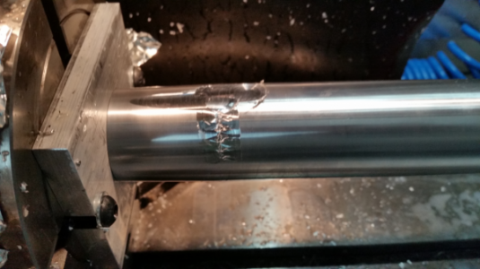
Well it was bound to happen sometime. I scrapped my first part. I started on the barrel guard and I think I was a little too optimistic about my setup.

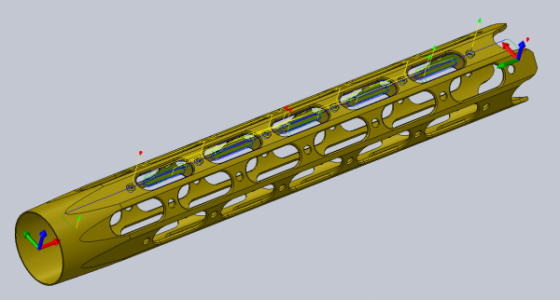
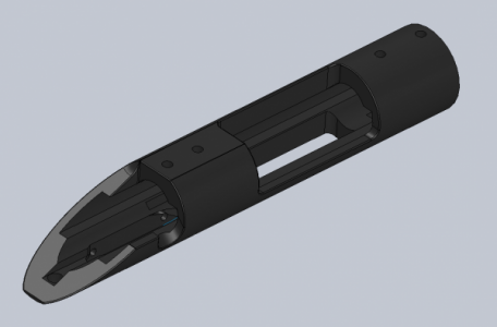
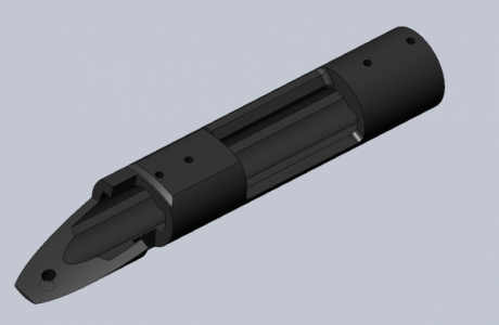
Here is the CAD.

HG_07.png

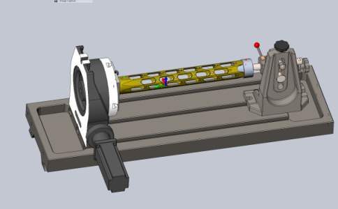
Here is the guard modeled in the fixture.

HG_08.png

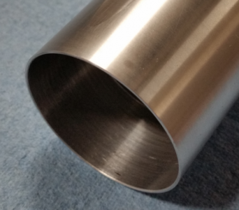
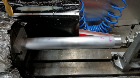
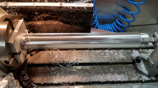
Here is the turned guard blank ready for machining.

HG_01.png

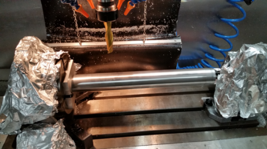
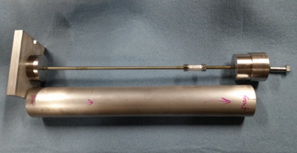
The guard is mounted between a plate that is attached to the rotary axis and a plug that rides on the tail stock taper. A threaded rod is between the plate and plug to hold the guard under compression. The guard at the plate end is tapered and is very thin. There was not enough surface area to properly grab the face of the plate.

HG_04.png

In addition my lead in speed was too fast, the lead length and lead radius were too small.

The end result.

HG_03.png

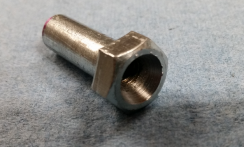
I remade the plug that is pressed into the plate with a larger OD that is a press fit into the guard. On the tail stock end I drilled out the center of the plug and made a Chicago bolt to go through the plug. The bolt head is counter-bored for the tail stock. This gives me greater clamping pressure.

HG_06.png

I also decided to not turn the OD and taper yet to leave a greater clamping surface.

Here is the revised fixture.

HG_05.png

Ready to try again as soon as I tweak some of the g-code.

HG_09.png
 
Things went pretty well today. I learned a few things but overall I'm happy with the result.

First op was to cut the flats on eight sides. I'm glad I modeled the fixture in solidworks. I caught a cut interference with the button head cap screws that hold the fixture to the rotary axis. I was able to change the lead out to avoid it.

HG_10.png

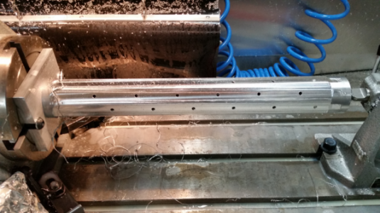
Next was drilling the holes.

HG_11.png

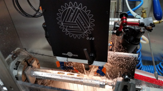
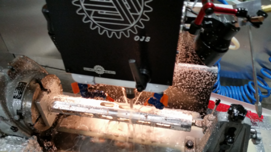
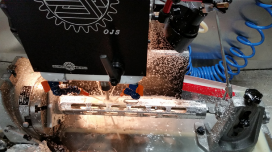
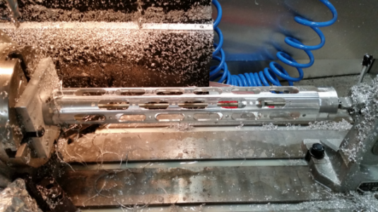
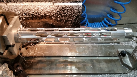
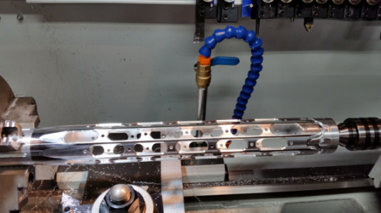
Next is milling the slots.

HG_12.png HG_13.png HG_14.png HG_15.png

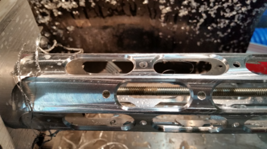
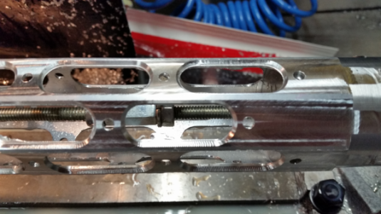
Next is the chamfer on the slots. I was getting some chatter out at the tail-stock end. At first I thought it might be because as the slots were being cut the torsional rigidity was being compromised allowing that end to twist a little. Turned out the tail-stock was not tight. Oversight on my part.

HG_16.png HG_17.png HG_18.png

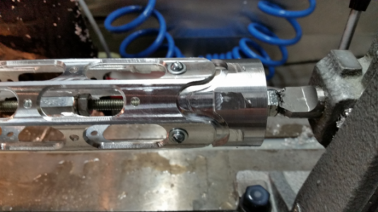
Final op on the 4th axis is the front contour. I couldn't figure out how to do this tool path in HSMWorks so I used Aspire for the CAM. I added some additional screws to keep the end plug from rotating in the part during cutting.

HG_20.png

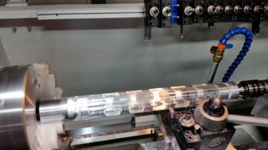
Off to the lathe to turn the final OD and rear taper.

HG_23.png HG_24.png

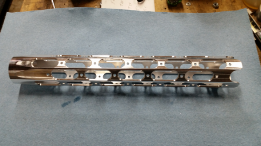
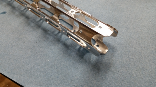
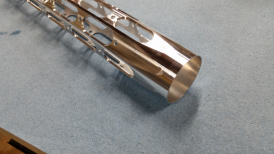
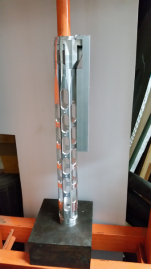
Completed part ready for final deburing.

HG_25.png HG_26.png HG_27.png
 
Things went pretty well today. I learned a few things but overall I'm happy with the result.

First op was to cut the flats on eight sides. I'm glad I modeled the fixture in solidworks. I caught a cut interference with the button head cap screws that hold the fixture to the rotary axis. I was able to change the lead out to avoid it.

View attachment 142418

Next was drilling the holes.

View attachment 142419

Next is milling the slots.

View attachment 142420 View attachment 142421 View attachment 142422 View attachment 142423

Next is the chamfer on the slots. I was getting some chatter out at the tail-stock end. At first I thought it might be because as the slots were being cut the torsional rigidity was being compromised allowing that end to twist a little. Turned out the tail-stock was not tight. Oversight on my part.

View attachment 142424 View attachment 142425 View attachment 142426

Final op on the 4th axis is the front contour. I couldn't figure out how to do this tool path in HSMWorks so I used Aspire for the CAM. I added some additional screws to keep the end plug from rotating in the part during cutting.

View attachment 142427

Off to the lathe to turn the final OD and rear taper.

View attachment 142428 View attachment 142429

Completed part ready for final deburing.

View attachment 142430 View attachment 142431 View attachment 142432

Very Nice!

Tom S.
 
Awesome work Jay. You make this look easy.
 
Here is the picatinny rail.

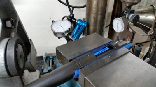
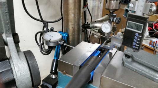
My original 3D model of the receiver was not correct so I had to spend some time drawing one with enough correct details to finish the picatinny rail model. I searched the interweb for dimensions of the radius of the rear bridge where the rear scope mount sits. It also sits lower than the front. Everyone I found was different and varied a lot so I figured out a way to measure it using a TDI in my drill press and a machine vise on a X Y table.

By zeroing the TDI on the center-line of the receiver and moving a measured amount right and left I could plot the radius. Height gauge was used to measure the offset.

Measure01.png Measure02.png

Here is the old (left) and new (right) 3D model.

Receiver_OLD.png Receiver_NEW.png

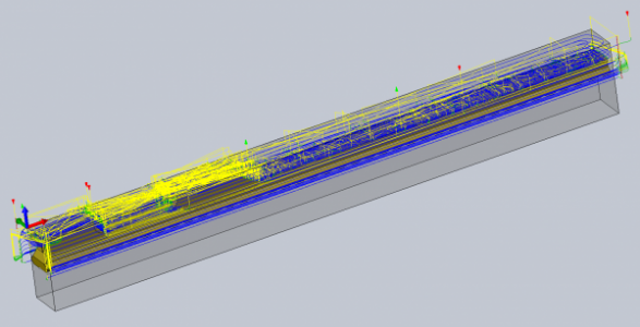
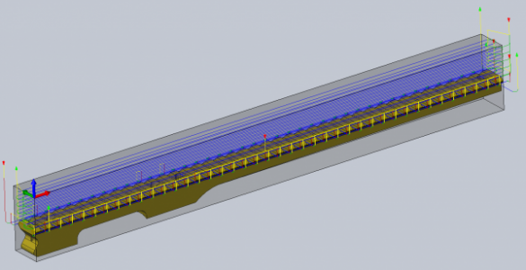
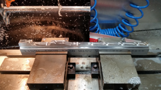
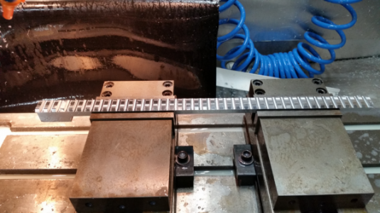
Machining of the picatinny rail. It was machined from 1" x 2" stock. The CAM was done with the model inserted into a model of the stock to set the coordinate origins for the top & bottom operations. The full rail is 22.2" long which exceeds my table travel so it was made in two pieces. The main piece shown here is 16.2" long

Tool paths.

PR-CAM01.png PR-CAM02.png

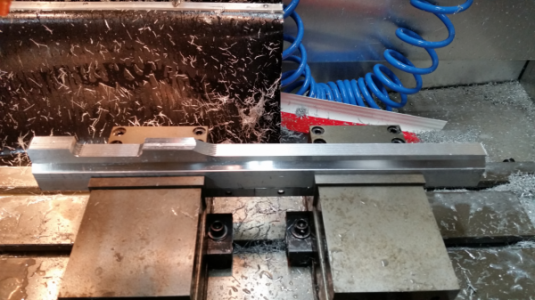
The bottom was done first. For the top operations the part can be held by the machined sides under the bevel and still have room for the cutting tools.

The rail has a built in 25 MOA slope when installed so all the bottom finishing operations were 3D tool paths.

After 3D adaptive roughing with a 0.5" 4 flute roughing end mill.

PR01.png

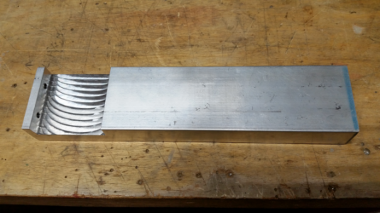
After the 3D horizontal profiling wth a 0.5" 2 flute ball end mill. Step over on the radius-ed areas that contact the receiver were done with a 0.012" step over. The balance was done with a 0.04" step over just because I like the look. When installed it is mostly hidden. The sides and bevel were done with a 0.375: drill mill.
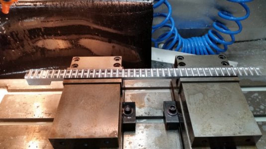
PR02.png

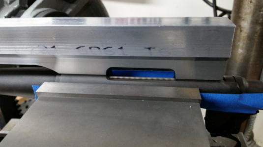
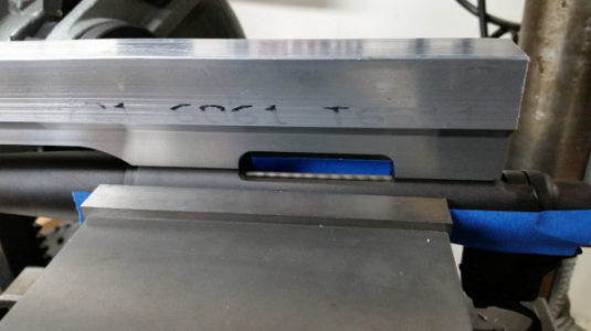
Test fit on the receiver. Perfect! Unfortunately there is a shadow at the base so it does not show well in the picture.

PR03.png

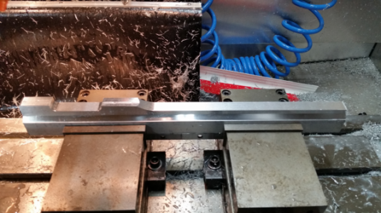
Now the top.

PR04.png

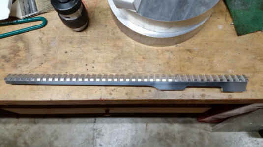
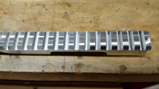
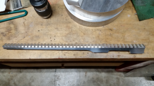
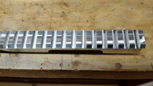
Finished rail.

PR05.png PR06.png

PR02.png

PR03.png

PR04.png

PR05.png

PR06.png
 
Before I can drill the mounting screw holes in the picatinny rail I need to assemble the hand guard and double check the measurement from the receiver mount holes to the drilled holes in the guard just in case of error creep.

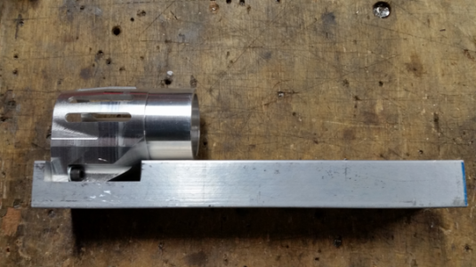
The guard is pressed onto the guard mount and they need to be indexed to each other. To do this I made a jig to hold the guard mount so that the flat on the guard could be used for indexing.

The jig.

Jig03.png Jig01.png Jig02.png

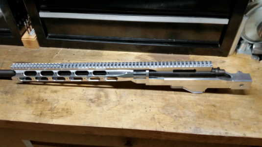
Here is the stock partially assembled to do final measurements for the scope rail.

JT7-01.png
 
You do very nice work Jay, your extra effort in detailing and posting is inspirational. Keep it coming!
 
All I can say is, WOW!

Tom S.
 
Back
Top