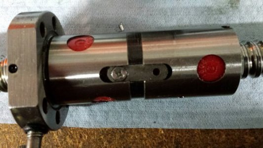
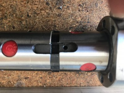
I'm resurrecting this thread because backlash has reared it's ugly head, again. While .0008" of backlash was acceptable after I chased my tail a couple of years ago it has come back to haunt me. As some of you know I recently moved and as of a couple of weeks ago had my machines up and running, except for the CNC mill. Finally got it operational this past week. Last time I used it was in late February and at that time the quality of my finished parts needed some attention. The first order of business was to tune it up before making chips.
First I adjusted the X, Y and Z gibs by snugging them up until the motors missed steps then I backed off the gib adjustment screw until each axis ran throughout it's travel smoothly and without missing steps. I found that backing off the adjuster 1/2 to 1 turn was about right. Next step was to check backlash. Whoa! .0065" of backlash on the X axis and .008" on the Y. I had a dial indicator mounted on the table with the tip contacting the spindle. Jogged the table to remove backlash, set the DI to "0", set Mach3 jog increment to .100" and jogged the table. The Mach3 DRO read +0.1000" and the dial indicator made one full revolution to "0". I then jogged the table in the "-" direction. The Mach3 DRO read 0.0000" and the DI moved .0935". Checked it several times and it was repeatable. So where is the backlash coming from? Tight gibs, incorrect AC bearing preload, loose drive coupling, bearing/motor mounts flexing?
I decided to check the AC bearing preload so I disassembled the X and Y bearings housings. The bearings looked good and were smooth rotating by hand. My goal was to get .004" to .006" of preload. I installed the bearings and inner race spacers in the bearing housing with a .002" to .005" shim between the outer races and tightened the retaining nut. Measuring with a dial indicator I noted the lateral movement of the ball screw and then added a shim the thickness of the lateral movement plus .004" to .006" shim for preload.
Well, this kind of worked. I assembled the the X axis and still got .0065" difference in readings between my DI and the Mach DRO. Next step was to check my bearing housing/motor mount for flexing. All was good there; no detectable movement with a .0005" DTI. Now it's gib adjusting time. I backed the front gib adjusting screw out 1/2 turn and snugged up the rear screw. Did my backlash check and got .005". This is looking up! I backed the gib adjuster out another 1/2 turn. Checked backlash and it got better, .0038". Another 1/2 turn out, ran the test and backlash stayed at .0038". Ran the adjuster in 1/2 turn and checked backlash at .0038". Scratching my head trying to figure out where the slop could be when it hit me that I didn't do a final ball screw lateral check after the last AC bearing shim pack adjustment. I mounted my DI to the table and set the needle on the end of the ball screw. Jogged it in one direction, set the DI to zero, and jogged it the opposite direction. Voila! .003" of ball screw movement. I'll add a shim tomorrow and re-check before moving on to the Y axis.
I'm writing this long description to explain how I approached this problem so others can see what I did and to get feedback from the Hobby-Machinist brain trust on how I could have done it differently and/or better.
Thanks for reading.


