ARC-170's Craftsman 101.07403 lathe restoration thread

HEADSTOCK REMOVAL
25. I'd like to take the headstock off the ways and thoroughly clean and paint it and the ways (easier to do in pieces), but my research indicates it is not an easy task to realign it. Found something called "Rollie's Dad's Method of Lathe Alignment". Anything else out there I can look at? Anything I should know about re-aligning it before I take it off? The MOLO didn't have anything.

I think I need to check the headstock alignment anyway, but maybe it's better to check it BEFORE I take it apart; if it's fine, then maybe leave it alone and try to paint the machine assembled? Thoughts?

I've heard it isn't an easy task to re-align the headstock to the ways, but it sounds interesting and challenging. I just want to make sure I'm not getting in too far over my head, or asking for trouble. I have a machinist's level (it was my grandpa's) for the ways, which I plan to use when setting up the machine once it's cleaned.
 
At least as I recall it, back in the day, Varsol (the word or name) had become a catch-all name to mean any of several slightly different solvents commonly used for parts cleaning. Another less common one that was also used as a generic name was Stoddard Solvent.
 
Last edited:
25. I have never actually done a headstock removal but I did sell the 54" bed off of a Craftsman Commercial to someone who wanted to convert his 12 x 24 to a 12 x 36 and he had no particular issue with removing the headstock. So it wan't a press fit. Beyond that, I don't know how tightly they fit between the ways. I would suggest not removing the headstock casting unless there is some good reason to do so. If you do remove it, I would have a pair of studs or 2" to 3" long lengths of All-Thread to screw into the two positioning screw holes to set the left-right position. If, after fully seating the casting between the ways, the studs are not free turning in the tapped holes, move the casting left or right until they are. Then remove them and immediately install the two screws. You will have to reassemble the headstock before you can use any method that I know of to check the angular alignment.
 
SPINDLE BEARINGS
22-23. I took these to the head of the adult school machine shop and he told me they looked fantastic for being 75 years old. He told me they looked like they didn't have much wear, either. The stains are from the grease just sitting there for many years. The bearing races are smooth. The surface of the spindle is as well. I soaked the spindle bearings with kerosene and wire-brushed by hand the dried grease/oil. I used compressed air to blow out the debris. I did this about 3 times. Next I'm going to oil them up and reinstall them.

HEADSTOCK REMOVAL
25. I decided to take the headstock off my "donor" lathe, since I want to part it out. It was pretty straightforward. I loosened the two screws at the back and the main one in front, tapped the headstock with a mallet ( there was wood between the mallet and the headstock) and it came right off. The ways and bottom of the headstock are machined, and there is little or no play.

I think for now I will leave the headstock on my lathe. I want to assemble it and make sure everything works before taking it apart to paint it.

OBSERVATION OF INTEREST (TO ME ANYWAY)
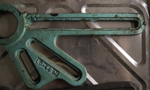
26. The bracket (part #L3-58M), looks like it broke and was welded. As you can see on the long slot, there are welds at either end. The donor lathe has a good one, so I'll use that. Thought maybe I'd file and machine the slot on this one at some point.
IMG_1482 lathe bracket small.jpg
When I took the carriage off, it had some different hardware and the miter gears looked like they had been replaced (I found a broken one with a bunch of parts). I also found a broken bearing (the one that goes on the right side) for the lead screw. I think this lathe might have been "crashed", then repaired. Everything else looks fine.

Also, the paint appears to be not original. I found some blue paint under the bearing covers on the headstock and a little trace under some other parts when I scraped them. I find it interesting that the green paint is over the welds as well. I've not found blue paint anywhere else, though, even under parts that could be moved, but maybe weren't if this was painted by someone too lazy or in a hurry. If this was re-painted, whoever did it, did a thorough job. The color really doesn't seem like it was done in 1944; the metallic-ish green is more 1970's to me. I think I've seen pictures and posts that have this machine being a dark blue.
 
22-23. Sounds good. Do NOT apply grease to the bearings prior to re-assembly. It will eventually harden and Murphy says that it will harden in such a position as to prevent oil from the oil cups from getting into the bearings.

26. Yes, I would use the unbroken change gear bracket from the donor.

COLOR. AFAIK, Atlas on their 6", 9" and 10" used only dark machinery gray from the beginning until sometime in the 1950's when they changed to machinery gray. The only other color that they used AFAIK was an irritating blue on the 10100 and 10200 MK-2 6". Sears, on the other hand, used too many different colors to keep up with, up until 1957 when they also changed to machinery gray. They remained machinery gray until production stopped in 1974 on their 6" and in 1981 on both Atlas and Craftsman 12".
 
COUNTERSHAFT DISASSEMBLY
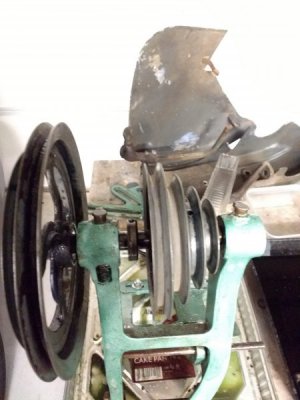
27. Having a hard time getting the two pulleys off the countershaft. I've loosened all the set screws on them and the collars and can turn the shaft using the bigger pulley about 15 degrees either way; it won't turn anymore then that. There's a key in the smaller pulley that I cannot see, but can see the keyway. Could the smaller pulley just be stuck? I've got it soaking in penetrating oil for now. I tried hitting the shaft with a wood dowel and hammer and it didn't budge.
IMG_20190420_200010296.jpg

RIVET/NAMEPLATE SCREW REMOVAL
28. Is there a trick to getting these off? I've seen nameplates for sale with what appear to be original screws. I thought I'd try visegrips, but thought I'd ask before I attempted anything. I'd like to take off some of the nameplates at some point so I can paint the piece they are attached to. I don't care for the "taped off" look.
 
Most of the Atlas nameplates that I have seen or seen photos of are affixed with what are called "drive screws". They can be identified by having a round head with no screwdriver slot. They also look like the head of a round-head rivet, but you won't find the peened end on the inside. If you are lucky, the hole that they are driven into will have been drilled through. These can be driven back out with either a pin punch or a short piece of drill rod which are small enough to be a slip fit into the hole.

If the hole was not drilled through, your only options are don't remove the plate or drill them out. The latter choice is easier said than done, especially on the end of the bed which probably can't be gotten onto a drill press. If you do attempt it and are successful, you can buy new drive screws from places like McMaster.com. Pray for them being drilled through.

I'll ask you to do one thing. Don't remove them and then lose interest in the project. There are far to many examples of that around.
 
No personal experience, but another option to remove drive screws is to use a Dremel cutting tool and fashion a slot in the head of the screw. Then use a standard slotted screwdriver to get them moving. I agree that tapping them out from the back is preferred.

Craig
 
27. I gave up trying to get off the pulley and big pulleys on the countershaft. I tried a puller, but this just bent the pulley a little. The smaller pulley moved a little. I decided I'd like to get the machine running for now, make sure everything works, then paint it at some point. I bought it to make chips! So, I cleaned it with Simple Green, wiped off the oil and put it back on the machine. I will lube it next.

28. I was going to try the make-a-slot-with-a-Dremel, but thought I's see if there was another way. I think I'll leave them on for now.

BACKGEAR DISASSEMBLY
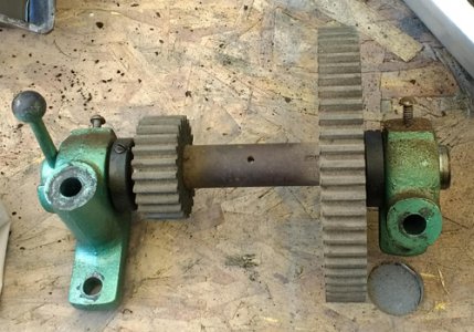
29. I'm having a hard time figuring out how to take apart the back gear. I can get the right bracket (green part on right, L4-245L) off real easy. It looks like everything is press-fit together, so what do I pull or push apart first? I loosened all the set screws and then tried to move the gears, but they wouldn't budge. I'm not sure I want to use a puller on Zamak.
I may just clean this up and re-install it, but I wanted to at least ask so I'd know.

30. Also, there were shims on the brackets. I saved them and know which ones go on which side. What are these for? Aligning the shafts of the main spindle and back gear? How critical is this and how do I tell if they are good? Does the MOLO have anything?
lathe backgear.jpg
 
29. As a general rule, back gear isn't engaged too often. However many operating hours are on the machine, probably no more than 5% were in back gear on most machines. Oil the eccentrics and the shaft and bushings and confirm that everything moves freely without much slop. And put the thing back on the headstock.

None of either the 10" or the 12" drawings actually show them but the headstock section view drawing in the MOLO does show them. The shaft is pinned to the eccentrics. Most of the 6" parts drawings show this, with a 1/8" roll pin at the handle end and a 1/8" taper pin at the other end. If you can, you might easure the diameter and length. Late in life, Atlas did do Technical Bulletins on disassembly and assembly of the headstocks. These are all available in Downloads. Although the section view of the headstock and back gears do not show the roll pin at the handle end, they do show the groove pin at the other end.

30. The MOLO unfortunately does not mention back gear lash and neither do the technical bulletins. However, the four back gears are similar to the change gears, where it is mentioned. The purpose of the shims under the two back gear mounting brackets is to adjust the gear lash. As with the change gears, use a strip of heavy brown wrapping paper or 24 pound bond printer/copier paper for the adjustment. Cut a strip of paper about an inch wide. Pull out the Direct Drive Pin and engage back gear. While turning the spindle, feed the paper strip into each back gear pair, one at a time. With the paper between the gear teeth, rock the gears back and forth, watching the relative motion between the back gear and its mating spindle gear. Make this test about every inch of circumference of the larger gear. If there is obvious relative motion between the two gears, repeat with the other pair. Assuming that both gear pairs had about the same lash all of the way around, remove the paper, remove the back gear assembly, remove one 0.002" shim from each pack, reassemble and repeat the test. If there is still obvious gear lash, remove a 0.003" shim from each side and reinstall the 0.002" ones. Repeat the tests until there is a noticeable drag when feeding the paper strip into either pair. Remove the paper and confirm that the pair has just discernible gear lash all of the way around. Color that one done and continue with the other pair.
 
Back
Top