ARC-170's Craftsman 101.07403 lathe restoration thread

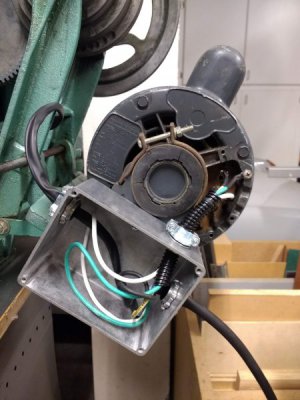
32. Here's my solution:
IMG_20190501_125148148.jpg
I got a box at Fry's Electronics that was nicer than the household ones at the home improvement stores. It has a cover; I left it off for the pictures. I also got a long length of heat shrink tubing. I then got some colored wire and wire clamps at Home Depot. The power cord comes in from the right. The wires for the switch go out the left to the headstock. The wires on the top go to the motor. I may re-do the motor wires with some heat shrink so everything looks the same and nice and tidy.

The box is attached to the motor bracket with a screw and plate. I didn't drill any holes on the motor bracket; there's a hole in it already.

I went to a local motor shop and they didn't have a cover. We tried about 10 different ones. I was going to make one, but came up with the solution shown.

I looked into right angle connectors, but once I came up with this, I didn't think I'd need them anymore. Also, the orientation and location of the tabs is such that the wires would still have to bend a bit tight to get out if I put a cover on this.
 
33. Sometimes you just have to bite the bullet and pay someone who knows what they are doing to fix something. That is what I would do .

I paid a local welder $45 to fix it. Took about 15 minutes. Apparently, cast iron welding rods aint cheap.
 
Good deal. That's still probably less than a used replacement would have cost you.
 
SPINDLE RE-ASSEMBLY
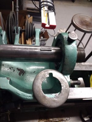
34. How is this done?! I cannot get the Woodruff key AND bull gear pulley, small gear and collar on at the same time. There is not enough room to move the spindle far enough to the right to allow space to get the rest of the parts on it because the key needs to be in place and it hits the dust cover. None of the parts on the spindle fit thru the holes in the head stock. I can't put the key in the slot, then insert the spindle thru the right hole, either because the hole in the dust cover doesn't have enough clearance (it's about 0.06" too small). I remember the key just sort of coming out, but I cannot seem to get it to go back in. I've tried tapping it in as I push the gear. Is there some trick to this? How was this assembled when new? The instructions for removing it just say to reverse the process. Maybe I need another set of hands?

The previous owner cut a notch in the dust cover. I bought another one without the notch, but I see why this was done. The donor lathe I have doesn't even have a dust cover on the inside right bearing hole. Again, I can see why.

IMG_20190502_202435984.jpg
 
Try with everything on the spindle (including the collar that is to the left of the small spindle gear) pushed as far to the left as they will go. And with the keyway in the bull gear and the spindle keyway at 12:00 o'clock. Move the spindle back to the right from where it is in your photo. Hold one end of the key with longnose pliers or etc and stick the other end into the keyway in the spindle. With a hardwood or soft aluminum stick, try to force the key down and rotate it 90 degrees as you tap it down into the spindle keyway and to the rear up under the keyway in the bull gear. The inner dust covers must both be in place, along with the bearing cones, before you start.
 
34. Got it! I was overthinking it and trying too hard. I put all the parts on the shaft and installed the dust covers, then put the key in the slot so the right side was sticking up. As I tapped the shaft in, and pushed the key with my finger, it just slid right in. I was just practicing for doing it with pliers, but it just went right in. Everything just barely fits, but it will go in.

The hard part was figuring out how to get the collar on the left against the shoulder on the shaft. I made a wood spacer (u-shaped) to go between the collar and the left dust cover. As I tapped the shaft it pushed the collar against the dust cover, seating them both.
 
OK. Glad that one came out good.
 
SPINDLE ALIGNMENT
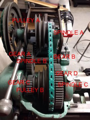
35. In the process of reassembling the spindle and gears on the head stock, I noticed they are not aligned. What is critical to have aligned, and what is not critical?
lathe headstock alignment with letters.jpg

Here's what I can and can't move:
I can move spindle A and pulley A.
I can't move spindle B much, maybe 1/16", same with gears A and B on it.
I can align the gears on spindle B to spindle C, but not perfectly; they are maybe 1/16" off. If the gears are aligned, the belt is not and vice versa.
Spindle C is pretty much set, but I can move gears C and D and pulley B.

How far off can the belt be mis-aligned?
 
First, follow the instructions in the Technical Bulletin in Downloads to preload the spindle bearings (if you haven't already).

Slack the belts and pull out the direct drive pin.

Then check that the collar to the left of gear "C" is up against the shoulder in the spindle between the collar and the gear.

Check that the spindle pulley "B" has around 0.005" end float and turns freely. Adjust the position of the bull gear "D" if necessary.

Engage back gear and if there is mis-alignment between each pair of gears, move the back gears if you can to achieve this or the best compromise.

If the countershaft cone pulley "A" isn't lined up with spindle cone pulley "B" and if you can, move pulley "A" to achieve this.

Check that the motor pulley and the large 2-step countershaft pulley are aligned. If necessary, move the motor pulley.

If you haven't already, lubricate the countershaft and the spindle pulley "B".

Disengage back gear, push in the direct drive pin, and tighten the belts.
 
SPINDLE ALIGNMENT (CONT.)
35.
A. First, follow the instructions in the Technical Bulletin in Downloads to preload the spindle bearings (if you haven't already).

B. Slack the belts and pull out the direct drive pin.

C. Then check that the collar to the left of gear "C" is up against the shoulder in the spindle between the collar and the gear.

D. Check that the spindle pulley "B" has around 0.005" end float and turns freely. Adjust the position of the bull gear "D" if necessary.

E. Engage back gear and if there is mis-alignment between each pair of gears, move the back gears if you can to achieve this or the best compromise.

F. If the countershaft cone pulley "A" isn't lined up with spindle cone pulley "B" and if you can, move pulley "A" to achieve this.

G. Check that the motor pulley and the large 2-step countershaft pulley are aligned. If necessary, move the motor pulley.

H. If you haven't already, lubricate the countershaft and the spindle pulley "B".

I. Disengage back gear, push in the direct drive pin, and tighten the belts.

A. Done.
B. Done.
C. Done.
D. Done.
E. I did this and got it to where I think it's good enough.
F. How mis-aligned can these be? Is it okay for the belt to track a little off?
G. Done.
H. In progress. I want to get everything lined up before I lube.
I. Will do once I get everything else lined up.

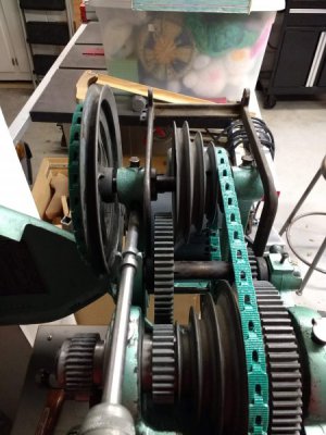
Here is everything lined up. I still need to move over the big pulley on the left to close the gap between it and the mounting bracket.
lathe pulley alignment.jpg

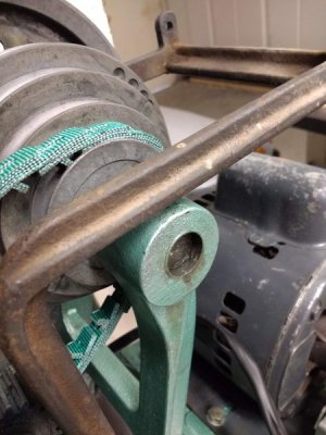
However, the motor spindle (spindle A) does not go all the way thru the hole in the bracket as shown is this image. Is this a problem, or can I leave it?
lathe pulley axle.jpg
 
Back
Top