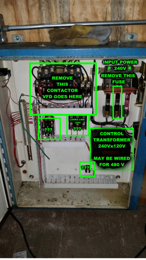
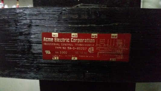
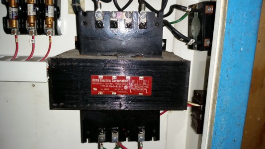
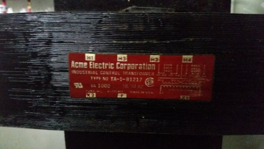
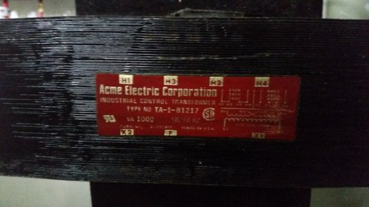
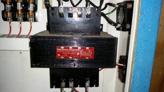
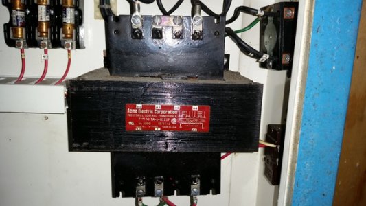
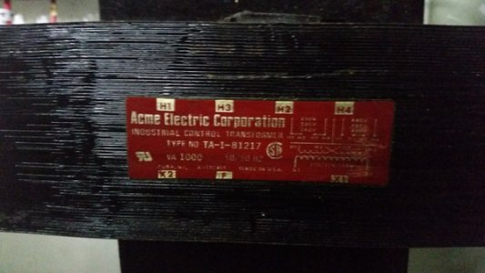
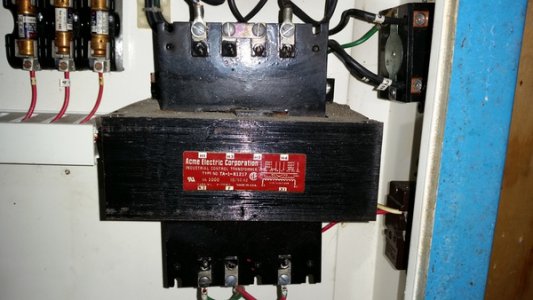
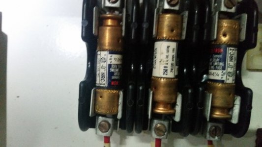
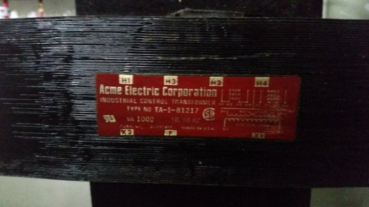
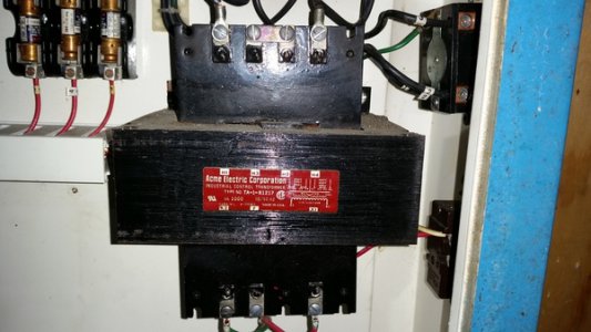
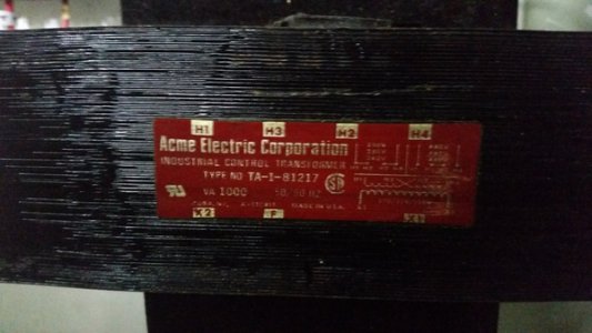
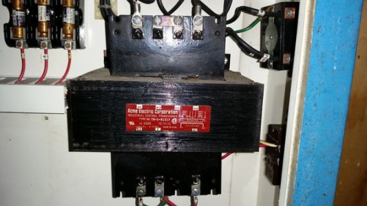
That's interesting. Looks like the mill was wired for 480V, so you are going to have to wire the motor for 240 volts and switch the transformer to 240V. On the transformer, there should be 2 link bars between the center screws, you just need to connect it like the diagram on the transformer.
The motor should be a dual voltage 230/460, 9 lead motor. Right now, I expect that the incoming power wires are connected to L1-1 ,L2-2, and L3-3. and 4-7, 5-8, 6-9 are connected respectively for 460V. For 240V, you would connect L1-1-7, L2-2-8, L3-3-9, and 4-5-6 connected together.
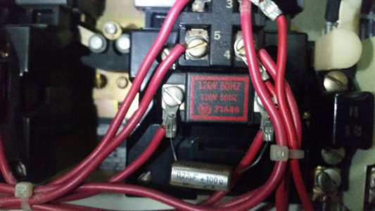
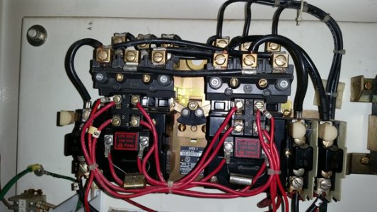
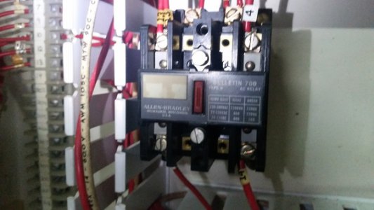
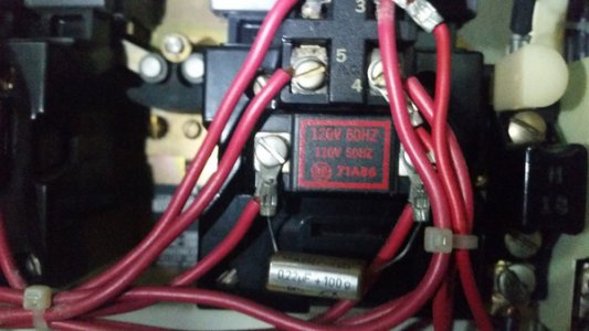
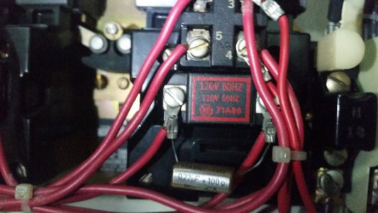
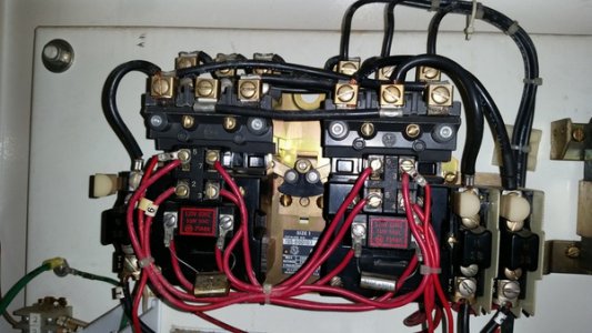
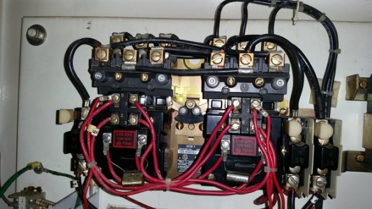
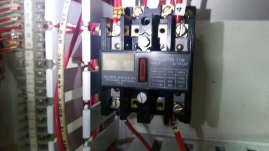
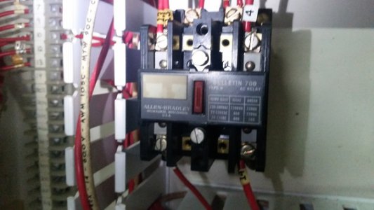
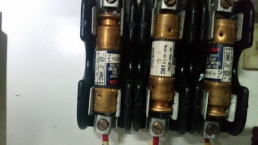
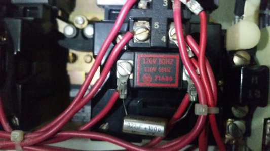
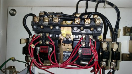
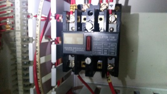
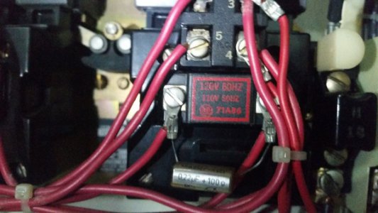
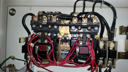
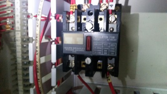
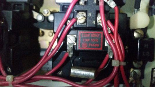
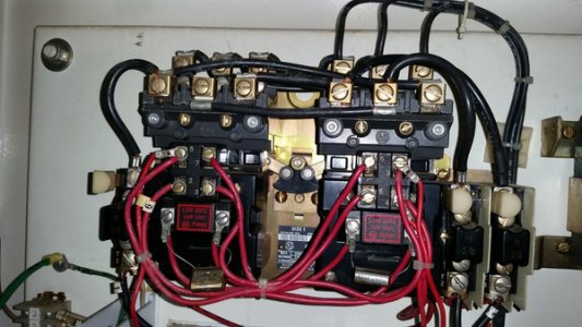
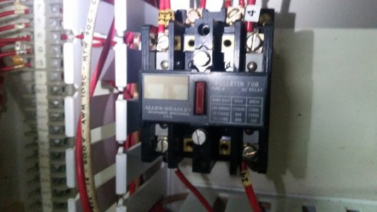
The relay (spindle motor starter) coils are 120V, but they were switching 480V. The spindle motor starter is a reversing starter with an interlock to prevent the possibility of engaging forward and reverse at the same time, that's why it's so complex looking. It's really just a 2 way switch. The VFD replaces all of that. 2 wires in one end (from power), and 3 wires out the other end (to the motor), plus the grounds of course.
The power end of this machine is really simple. The controls side is going to be more interesting and figuring out how the control side and the power side interact is going to be fun without a wiring diagram. The good news is that all of the wires in the power side are numbered, so not to bad to trace,
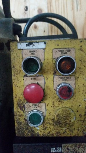
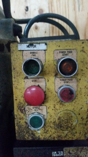
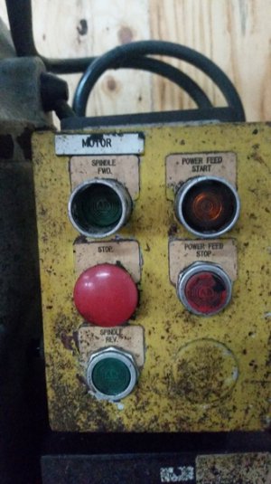
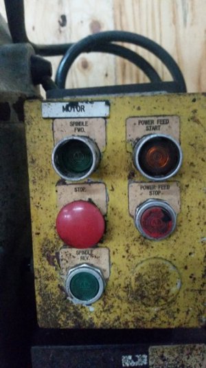
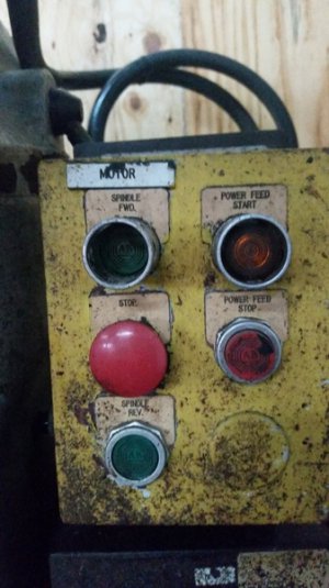
You should be able to use your existing buttons for the VFD. I have not downloaded the manual yet, but I will so I can work through this with you. There should be a way to wire a 3 button control with E-stop. We're going to make a controls engineer out of you.

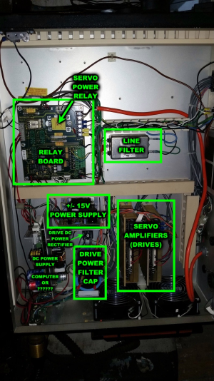
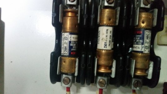
What we need to figure out is what powered up the servo drive system, the 1000VA transformer seems a bit light for that task, but maybe not. Earlier you mentioned running the controls end off of a 120V wall outlet, that is not a bad idea, that's the way I run mine. In that case, the only thing you would need in the power cabinet is the disconnect, the VFD, and the E-stop relay.
.
.
