-
Welcome back Guest! Did you know you can mentor other members here at H-M? If not, please check out our Relaunch of Hobby Machinist Mentoring Program!
- Forums
- THE PROJECTS AREA
- PROJECT OF THE DAY --- WHAT DID YOU DO IN YOUR SHOP TODAY?
- Project of the Day Mega-Thread Archives
You are using an out of date browser. It may not display this or other websites correctly.
You should upgrade or use an alternative browser.
You should upgrade or use an alternative browser.
2019 POTD Thread Archive
- Thread starter GoceKU
- Start date
- Joined
- Nov 23, 2014
- Messages
- 2,634
POTD was finishing up the destruction part of our testing on the ball sockets of a lift-gate strut (Chevy Traverse/Buick Enclave). The design spec is a minimum of 4000 N or about 900 lbs. Our biggest force gauge goes to 500 lbs., so brushed up on my Statics for some mechanical advantage. Test rig pictured below.POTD was making an arbor to do some testing at work on a lift gate strut assembly. We have a pretty good Tool Room, but they’re swamped so did this project at home.
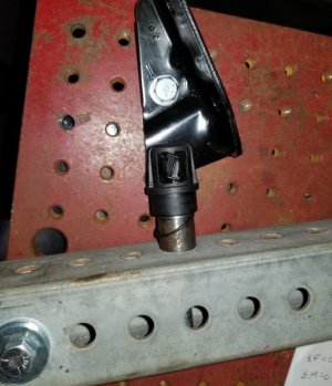
Plastic ball socket end of a lift-gate strut. Needed to make
an arbor that screws into the end for a pull until it breaks test
View attachment 293968
We’re going to be pulling on the end of a lift gate strut until ultimate failure. Plan is to thread an arbor into the plastic ball socket end of the strut and pull with a force gauge until something breaks.
First step was figuring out what the thread is in the ball socket. I did manage to check the thread with a thread gauge (1.5 mm pitch thread), and could caliper the diameter (18 mm), but used a product called PIG epoxy putty to make a splash of the inside of the ball socket detail. I started by giving the inside a shot of LPS 1 greaseless lubricant for a mold release. I’m guessing WD-40 would work as well or something similar. Cut off a length of putty, kneaded it, and mashed it into the socket using an arbor press to pack it out. Didn’t show it, but put a drywall screw into the putty and packed more around the screw for something to grab onto when unscrewing the splash.
Tight fit, but thread checked at 1.5 mm pitch
View attachment 293969
PIG epoxy putty used to make a splash of the strut end detail
View attachment 293970
Kneaded the putty, then mashed it into the detail with an arbor press
View attachment 293971
Stuck a drywall screw into the putty for reinforcement and
built up the area outside of the socket for something to grip
View attachment 293972
The putty took about 15 minutes to set up rock hard. It unscrewed pretty easily and did a really good job duplicating the inside of the socket. Confirmed the OD at 18 mm (~0.705”) and a thread pitch of 1.5 mm.
Used LPS 1 as a mold release. Epoxy splash unscrewed easily
and was a pretty accurate match of the internal thread.
View attachment 293973
Chucked up a length of ¾” what I thought was CRS (turned out to be drill rod . . .), faced, turned to diameter and relieved the base where the thread would end. Chamfered the start of the thread.
face and turn to diameter
View attachment 293974
relieve base of threaded area
View attachment 293975
chamfer start of the trread
View attachment 293976
Did a scratch pass for the 1.5 mm pitch thread and verified with a pitch gauge. Then proceeded to single point thread the M18 x 1.5 mm pitch thread. I used the plastic strut detail to verify the thread.
Verified 1.5 mm pitch. Really like my G0709 lathe with a
universal QCGB. I can switch between English and metric
threading without fiddling with the quadrant gears. Just
have to remember to leave the half-nut engaged and
reverse the lathe for each pass.
View attachment 293977
last pass
View attachment 293978
verified the thread with the strut cap
View attachment 293979
Parted off the arbor and flipped it in the lathe. Faced, chamfered the back side, center drilled, tap drilled and tapped a 5/16”-18 hole.
"Love" parting drill rod - lots of oil and low speed
View attachment 293980
flipped and chamfered
View attachment 293981
center drilling
View attachment 293982
tap drill
View attachment 293983
tapped a 5/16"-18 for an attaching bolt
View attachment 293984
Plan is to bolt the ball stud that the plastic ball socket snaps to onto a fixture plate. Run a bolt through one end of a piece of steel rack tubing we have on hand with pre-drilled 1” spaced holes for a fulcrum point. Then bolt the arbor to the lever 4” from the fulcrum. Then bolt the force gauge (our gauge goes to 500 lbs.) 20” from the fulcrum. The ball socket is supposed to take a load of 4000 N or about 900 lbs. This set up will give us a 5 to 1 mechanical advantage so we’ll be able to put a max load of 2500 lbs. on the ball socket. I’ll shoot a photo of the set up when we start breaking things at work!
Finished arbors (made 2) and the epoxy thread plug
View attachment 293985
Thanks for looking,
Bruce
Steel tubing pivots on a bolt into a fixture plate at the bottom.
Ball socket and my arbor are hard fastened to the tubing, ball socket
clips to the ball stud bracket which is attached to the fixture table with
a through hole/bolt so it can pivot. Force gauge is attached to the
tubing and fixture plate with a turn buckle. Put tension on the ball
socket by turning the turn buckle until the ball socket went "POW".
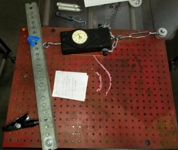
Statics equation for the mechanical advantage.
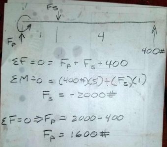
Put a rag and a plastic box over the ball socket and started turning the turn buckle. Loud "POW" when they broke . . . Read the force gauge and multiply by 4 for the actual fracture point. Minimum of 1100 lbs. in this case which exceeds the design spec of 900 lbs.
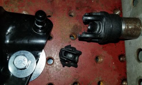
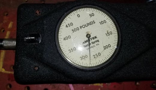
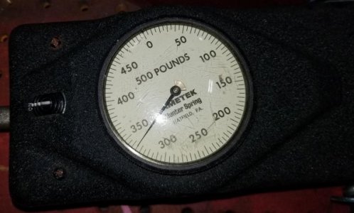
Next step is measuring the angles involved in the overall design. Then draw a free-body diagram to determine how much of a push up on the lift gate puts the strut ball socket at the 900 lbs. load (or 1100 lbs. in this case).
Thanks for looking.
Bruce
Last edited:
Posted part 2 of this video series. If you always wanted a speed handle and have a vice that’s not a 6” Kurt, that the commercial speed handles are made for, here is a method to make your self one. I’ve made several and had great results
Sent from my iPhone using Tapatalk
Sent from my iPhone using Tapatalk
- Joined
- Jul 14, 2017
- Messages
- 2,455
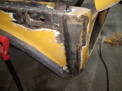
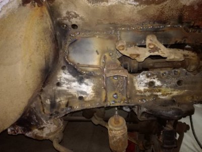
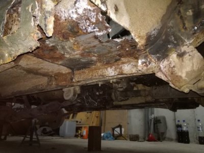
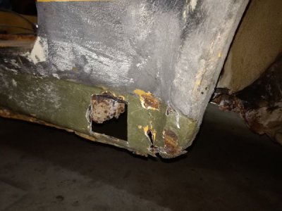
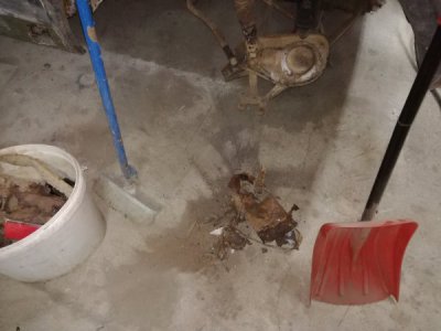
Today i continued welding on the little niva, i finish welding the front patch panel, also i place and fully welded the shock mount, this took couple of hours and the front corner will take a bit more bondo than the other side so i may call it bondo corner, then the dirty work come, i had to cut out all the rust from under, i also cut out a piece from the rocker panel to access it better and clean out everything i can access with a wire brush and sprayed it with anti rust acid. you can see some more pieces that i had to cut out on the floor.


- Joined
- Oct 21, 2014
- Messages
- 2,163
Well mad it into the shop for a little while today, (finally) did not get any machining done but did get a old 1920s Hit and miss running. Will be having to do some machine work for it in the future as have to make a choke plate, and some other small parts.
check it out will be placing any vids here
you tube
check it out will be placing any vids here
you tube
- Joined
- Sep 28, 2013
- Messages
- 4,395
Been pretty wiped out from long days at work and long rides on the bike, but finished up another chip shield for the mill. Nothing fancy, just some stainless angle and sheet, with a hard drive magnet screwed to the bottom.


the shields plus the baking trays on the mill table make clean up alot easier, especially when face mills are added to the mix! I also have an angled shield that goes on the top of the vise moving jaw.
the shields plus the baking trays on the mill table make clean up alot easier, especially when face mills are added to the mix! I also have an angled shield that goes on the top of the vise moving jaw.
- Joined
- Jul 14, 2017
- Messages
- 2,455
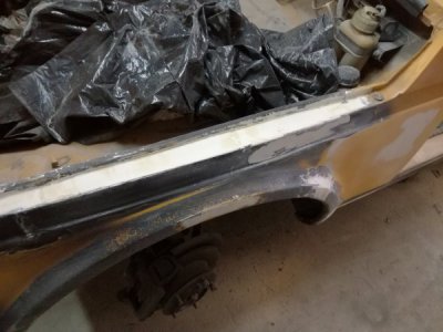
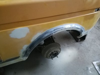
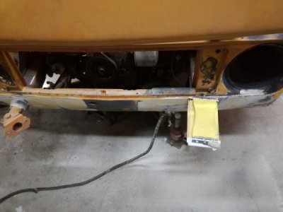
Today i had only few hours to spare but i made the effort to get something done on the little niva, it is starting to hold up other projects so i need to get it done and out of the garage. So i put on some fresh 4 grit sandpaper on my sending block and send down all the body filler spots, i also applied some more on some spots and from here i'll be hand sanding the rest of the bodywork, the DA sender is quick but i don't have the experience to take the right amount of without having to put some more on.


- Joined
- Jul 14, 2017
- Messages
- 2,455
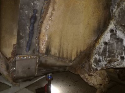
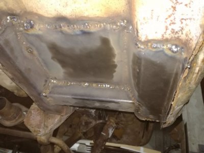
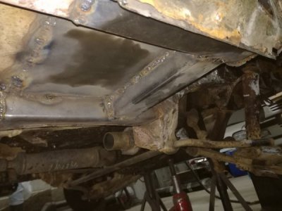
Today i had the day off, so i got stuck in the big garage and made the last of the big rust repair on the little niva, i had to form and shape pieces in couple of thickness and laid down about 1 kg of welding wire, i also welded in a piece of thick wall tubing to have something to jack against. Today was a hard dirty day, not fun welding upside down welding spatter burning me.


- Joined
- Nov 19, 2014
- Messages
- 991
I think you neededMaybe time for new stairs into my house
View attachment 294730
So... I think these will out live me. Probably want to wear shoes when using these.
View attachment 294731

