fixed a creaking problem on my bike that was driving me batty. 2 1/2h a day for 2 weeks of "eek, eek, eek" that was loud enough to make it embarassing to ride past school kids waiting for their bus. Had lots of time to think of a solution.
Problem - motor is not held in the frame in only one position, which allows it to shift and rub against the frame. You can see that the paint on the motor mounting pads has largely worn off and there's another worn patch just above the top one in the picture. The likely source of the noise.
the threaded ends of the bolts (drive side) had also started wallowing out the bolt holes, leaving "threads" in the softer material
The plan - bore out the drive side bolt holes to make delrin "top hat" bushings to press into the holes, keeping the bolts and motor away from the frame. On the other side, make longer top hat bushings that go through the motor, centering the bolts and space the motor away from the frame. Doing so would also require milling the thickness of the bushings (minus the considerable clearance from the factory) from the motor mounts on both sides.
First step, a piloted reamer/ boring tool out of scrap 01. The idea was to use both existing bolt holes to center the reamer and keep it perfectly aligned, then have it cut the new hole to a fixed ID. I've tried enlarging holes with a drill and it never comes out well.
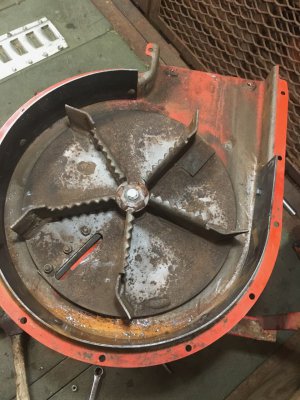
Here's the tool, couple of hours work on the lathe, mill and with a file. The fattest end will also debur the hole

Didn't bother hardening it as I figured it would be fine for the use and I was on a hard time limit - my ride in to work this morning!
in action
you can see the fretting marks on the far side where the motor is moving within the frame cradle. Tool worked well, really clean hole that was the same ID for all 3 holes.
Next step was machining down the motor mounts, after which I could work out the thickness of the bushings. As every single mounting point was a different thickness (~0.3mm from large to small) I split the motor and used the machined face of the case as a reference and clamped it to my mill table. First time using the clamp set, which was neat.
Then work out the amount to cut off the other side to get to the desired width, rebuild the motor then clamp it to the table using the 3 machined mounts as a reference surface. Clamping was a bit sketchy, but the cuts were small.
Widths came out to a range of 0.03mm, which was bloody fantastic.
Long top hat bushings, these go inside the motor where the bolts pass. Had to step ream out the bore as it was egg shaped - narrow at either end and widest in the middle where the case halves met. Probably something to do with casting the cases. These were a royal PITA to make, but eventually they fitted. Would have prefered a larger shoulder but I didn't have enough 1" delrin rod and I had 5ft of 1/2" delrin rod, so I used that instead
Measured again and made the top hat bushings for the other side, this was a failed one that came out too small
Ended up making the front one first and when I test fitted the motor there was more clearance than I liked. It was 0.15-0.2mm, as intended and down from 0.3-0.5mm as stock, but I reduced that to 0.1mm for the back two. No pictures of that as it was late and I was tired.
Finished product - you can see the larger top hat bushing on the right, but not the smaller but longer one on the left
This morning the first thing I said to my wife when I got to work was:
"Hello darkness, my old friend
I've come to talk with you again"
geddit?
Anyway, pleased as punch. A lot of work, but it came out just as I had planned, which is pretty satisfying. Only worry is that the motor will get hotter as it isn't directly connected to the frame any more. If that turns out to be a problem I can remake the longer top hat bushings out of alu instead.


