2019 POTD Thread Archive

While waiting for wood putty that was stained this morning to dry, I ran out to the "shop". Previously, a friend was making fun of me for my make-shift baton (3/16" stainless rod) when leading the music for a congregation (she kept calling it a "stick thingey" even though she knows what it is really called). I figured I had to up my game. So the trip to the shop was to grab some brass and turn a handle for that brass, then add a real point and a thread to the other end.

IMG_7869.jpg


It was simple and easy, but it was also a nice break.
 
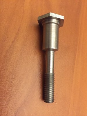
Made a collet draw bolt for my dividing head from a hardware store bolt. Pretty simple, came out decent.

The thread is 3/8 16. I started with a monster bolt and turned it down. The bolt size was chosen so the head would be larger than the backside hole on the dividing head. I turned the head thin so that it clears the base of the dividing head when titled straight up.

I did find it difficult to get good surface finish from HHS bits when turning. I'm wondering if the methods and material of the mass produced hardware store bolts makes them crappy for turning or if it's my bit geometry & technique.

Regardless, the final result does the job and I can now use my collet set with my dividing head.

IMG_3571.JPG

-Dave B
 
Finally able to get back in the shop for a little while before my surgery gets scheduled. Did a little cleaning and work on the Sattley Hit and miss engine.

Sattley flywheel

Trying to figure out how to insert a YouTube video here.
 
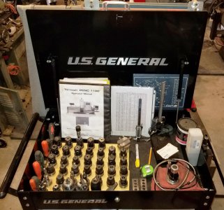
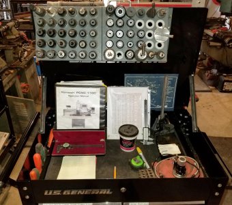
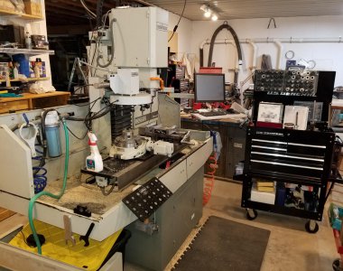
POTD modifying the Harbor Freight 5-drawer tool chest for my Tormach 1100 mill. I’ve got a Tormach tool holder on the mill chip pan that holds 21 tools, and a couple of Tormach wooden holders for an additional 42. I had a couple of 30-position 5C collet holders that used to be on my Clausing lathe, but it was upgraded to a 72-position holder, so the old 5C holders were gathering dust. Figured they work great on the lid of the HF tool chest for holding the Tormach tools.

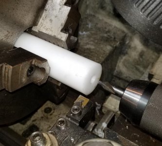
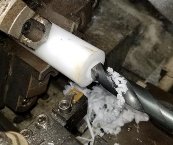
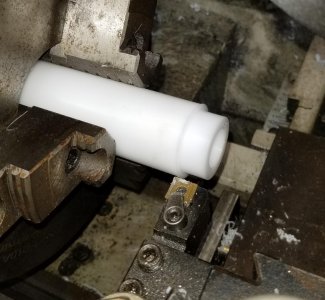
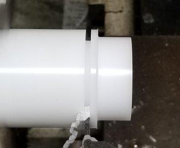
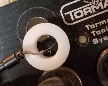
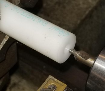
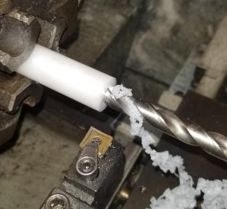
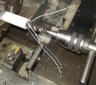
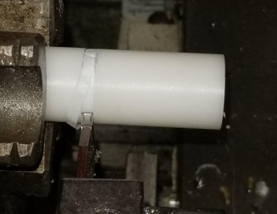
The 5C rack has a shade over 1.25” holes for the collets. Tormach’s TTS system uses tool holders with a ¾” shank. I had a 5’ length of 1.5” Delrin on hand, made up bushings to take the 1.25” holes down to 0.75”.

After the bushings were made, the tool chest lid gas struts were pulled and replaced with angle iron. The collet rack was set in place and mounting holes paint markered on the lid. Used a hole punch to knock in the mounting holes.

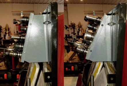
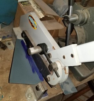
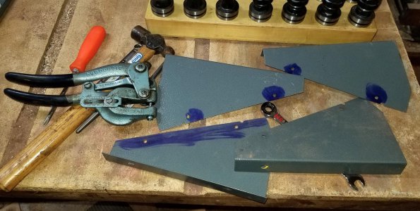
The 5C collets are heavy on the tail side, so they can be racked closer to vertical without falling out of the rack. The Tormach tool holders tend to be nose-heavy, so were all tipping down a little more than I’d like. Modified the side sheet metal pieces of the collet rack to a better angle, so now I can sleep at night.

Should work out great. Next big project for the mill will be making a full enclosure. I recently picked up a bunch of Creform tubing and fittings from Craig’s List. Plan on learning Fusion 360 during the winter and will make the stand one of my first design projects.


Thanks for looking, Bruce


BEFORE arrangement of my Tormach's tool chest
20190922_103936.jpg


Center drilled, 49/64" center hole, turned shoulder to ~1.27", and parted. Cleaned up the ends with a deburring tool.
20190921_123502.jpg
20190921_123622.jpg
20190921_124239.jpg
20190921_124349.jpg
20190921_124736.jpg


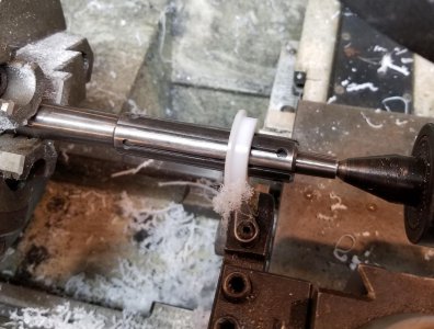
Had a few bushings too tight to fit into the 5C rack. Used an expanding mandrel to mount them and take off a few thousandths.
20190921_165027.jpg


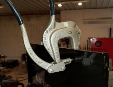
Transferred the 5C rack holes to the lid of the tool chest and punched holes with a Roper Whitney XX hand punch.
20190922_120842.jpg


Before and After side view of the rack mounted to the lid. I wasn't happy with the nearly flat angle the tools were at, so modified the sides of the rack to help gravity keep them in place.
20190922_124546.jpg
20190922_130003.jpg
20190922_132430.jpg


Rack in place on the lid and my Tormach's current set up. Full enclosure is in the near future.
20190922_140621.jpg
20190922_122957.jpg
 
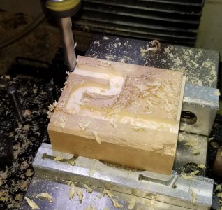
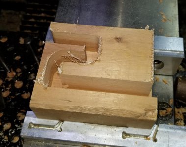
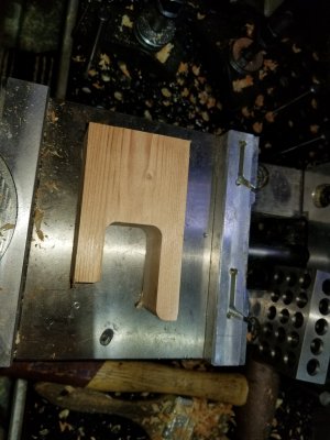
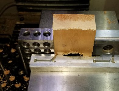
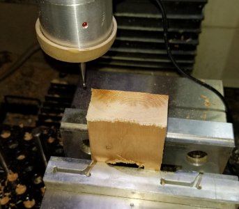
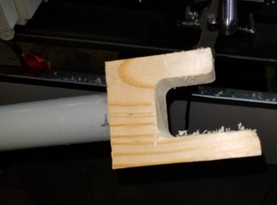
POTD was prototyping a flange bender for work. We have an Ergonomic issue on a part and need some mechanical advantage to help get the part properly seated. I took some rough measurements and made the prototype out of a 2 x 4 on my Tormach mill. Back to work tomorrow to see how it works. If okay, I’ll make up the final one from Delrin.


Thanks for looking, Bruce


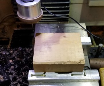
This Tormach is making me lazy. Using a probe to find the corner of the prototype 2 x 4 block
20190920_165526.jpg

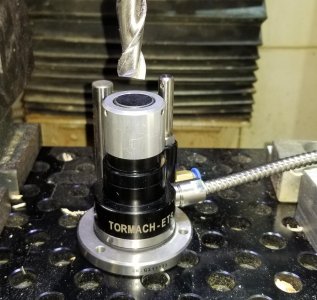
Still lazy, using the electronic tool setter to find the length of a deep-cut 1/2" end mill. Naturally, the CNC program needs to know the length of the tool so it cuts to the correct depth. It's really simple to use: Plug in the tool setter, change the PathPilot settings to ETS, go to the Probe tab in PP, type in a tool number, then click a button and the spindle drops until the ETS is tripped. For safety sake, I always manually trip the ETS ahead of time to make sure it's working.
20190921_101709.jpg

Prototype being cut
20190920_165655.jpg
20190920_165852.jpg
20190920_170121.jpg


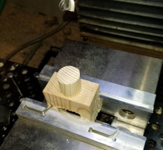
The flange bender will will get a handle. PathPilot has a conversational routine for cutting a boss, so no 4-jaw lathe work required. Set the block square in the vise with a 1-2-3 block, probed the corner to set up the coordinates, then let the CNC take over.
20190920_170205.jpg


20190920_170337.jpg
20190921_114812.jpg

Final prototype. We'll see how it fits up Monday. Easy to make tweaks as required with the CNC.
20190921_114906.jpg
 
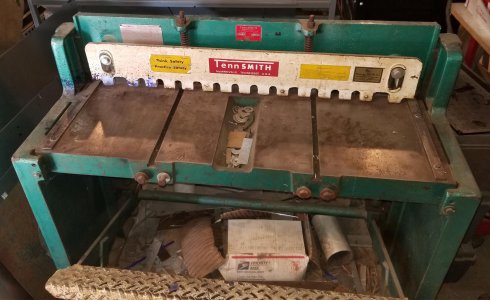
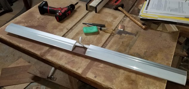
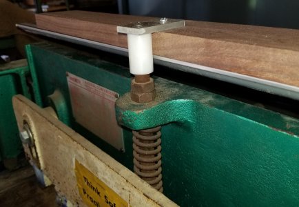
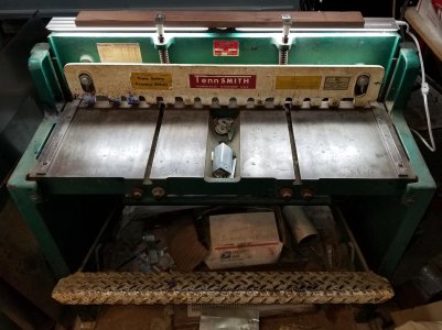
POTD was mounting a couple of 18” long LED under-cabinet lights on my 37” Tennsmith shear. Love the tool, but it’s tough to see a scribed line between the shear bar and work clamp. There’s a shop light directly overhead, but my head casts a shadow when peeking over the work clamp. Plan was to mount the 18” lights on a couple of ½” – 13 threaded rods that project above the shear bar. There are compression springs on the rods; the nuts up top are used to adjust the height and tension of the work clamp. The clamp sets above the shear and comes down to clamp the work to the table before the shear bar hits the material.

Turned a couple of bushings from ¾” Delrin. Tapped one side ½”-13, the other 10-24. I had some scrap Walnut in my kindling bin, used that to mount the lights to. The lights have a couple of keyholes for mounting. Ran screws into the Walnut and slipped the lights in place.

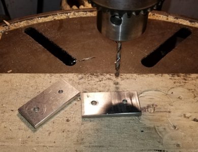
Cut a couple of brackets to tie the Walnut board to the Delrin bushings. Didn’t show the operation, but cut them on the band saw and sanded to a smooth edge.

Really nice to flip on the light and have no problems seeing a scribed or pencil line on the work.


Thanks for looking, Bruce


Tough to see between the white hold-down clamp and the shear bar just behind.
20190915_144030.jpg

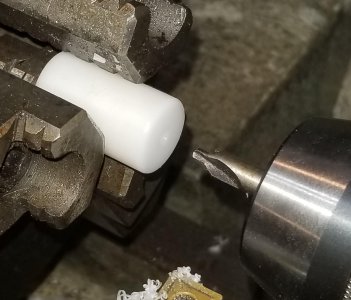
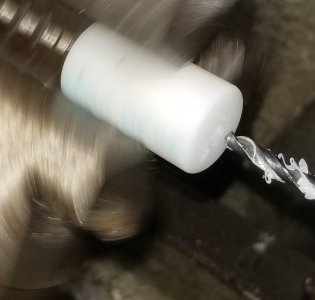
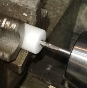
Making a couple of threaded bushings for mounting on the shear. Center drill, tap drill and tap a 1/2"-13 hole, then part
20190915_152502.jpg
20190915_152742.jpg
20190915_152906.jpg
20190915_153205.jpg

Flip the bushing, center drill, tap drill for a 10-24 thread, tap.
20190915_154008.jpg
20190915_154039.jpg
20190915_154148.jpg


LED lights mounted to the Walnut board. The Irish Spring soap is for the wood screws. Trick my dad taught me, use bar soap on the screws to lube them and not snap off as easily into the wood.
20190920_152658.jpg

Band sawed, sanded and drilled holes for the mounting brackets.
20190920_153243.jpg

Brackets, bushing, Walnut board and lights in place.
20190922_142514.jpg

20190920_154422.jpg

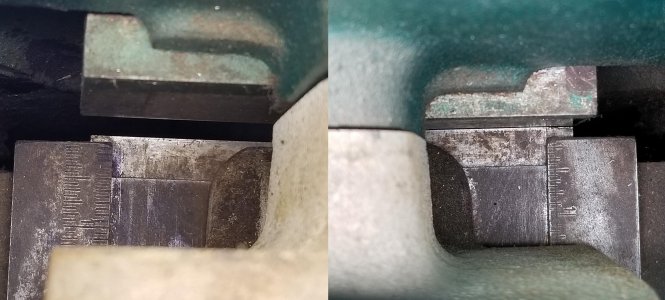
No problems at all seeing either ends of the shear's scale. My big head always cast a shadow and I was tired of using a flashlight to line up a mark on the work with the edge of the shear.
20190915_165425.jpg
 
Last edited:
I'm repowering an outdoor vacuum/chipper I made to an effectively unknown brand motor of the same size that I picked up cheap from PrincessAuto.

The old motor, a B&S 900 series, was working ok but the air filter just wasn't up to being able to handle the amount of dust the vacuum generates, and would plug up pretty quickly. I rebuilt it last year, but again had the same problem, and it's just not worth spending about 50% of the cost of a new engine in parts to rebuild it.

Today I worked on getting the impeller properly mounted on the crankshaft. The old crank is 1" OD, with a 1/4" keyway, about 3" long, and gets slightly larger near motor, and the impeller slides onto the crankshaft until it hits that slightly larger part, and a bolt going into the end of the crank holds it in place. The new crank is the same overall length, but it's 1" for most of the length, without a larger bit near the engine , the last 3/4" of the crank is reduced in diameter to 7/8", and has a 3/16" keyway.

To make the impeller mount properly on the new crankshaft, I bought a 3/16-1/4 step key, and then made a spacer that goes over the end of the crankshaft, both to make that last 3/4" of the crank be 1", but also has an extra 1" of length to space the impeller the same distance from the engines mounting surface.

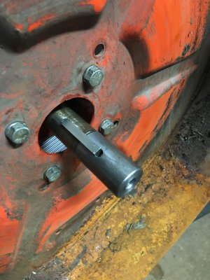
Pic of the spacer, installed:
IMG_1473.jpg

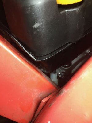
Also had to customize the gas tank a bit with a BFH so the chipper chute would clear it:
IMG_1474.jpg

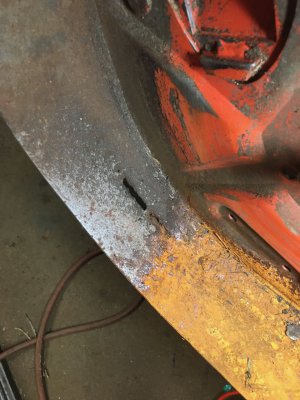
Still to do, it make a new liner for the blower housing. I previously made one from 16 gauge steel after wearing a large hole in the housing, and it's also worn through in a spot, so I'll make another one from a strip of 3" x 1/8" flat steel I bought. I'll also have to figure out how to get a larger air filter mounted onto the engine, to avoid another early death of the engine.
IMG_1475.jpg
 
I'm repowering an outdoor vacuum/chipper I made to an effectively unknown brand motor of the same size that I picked up cheap from PrincessAuto.

The old motor, a B&S 900 series, was working ok but the air filter just wasn't up to being able to handle the amount of dust the vacuum generates, and would plug up pretty quickly. I rebuilt it last year, but again had the same problem, and it's just not worth spending about 50% of the cost of a new engine in parts to rebuild it.

Today I worked on getting the impeller properly mounted on the crankshaft. The old crank is 1" OD, with a 1/4" keyway, about 3" long, and gets slightly larger near motor, and the impeller slides onto the crankshaft until it hits that slightly larger part, and a bolt going into the end of the crank holds it in place. The new crank is the same overall length, but it's 1" for most of the length, without a larger bit near the engine , the last 3/4" of the crank is reduced in diameter to 7/8", and has a 3/16" keyway.

To make the impeller mount properly on the new crankshaft, I bought a 3/16-1/4 step key, and then made a spacer that goes over the end of the crankshaft, both to make that last 3/4" of the crank be 1", but also has an extra 1" of length to space the impeller the same distance from the engines mounting surface.

Pic of the spacer, installed:
View attachment 302598

Also had to customize the gas tank a bit with a BFH so the chipper chute would clear it:
View attachment 302599

Still to do, it make a new liner for the blower housing. I previously made one from 16 gauge steel after wearing a large hole in the housing, and it's also worn through in a spot, so I'll make another one from a strip of 3" x 1/8" flat steel I bought. I'll also have to figure out how to get a larger air filter mounted onto the engine, to avoid another early death of the engine.
View attachment 302600

Could you make a snorkel of some kind and draw air from somewhere not so dusty when the machine runs?
 
Back
Top