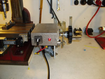
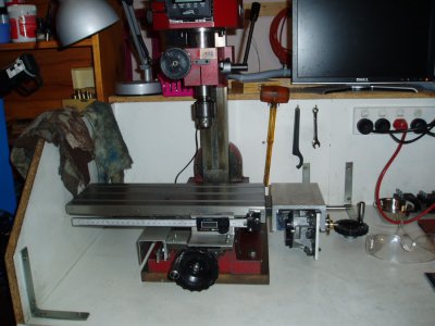
-
Welcome back Guest! Did you know you can mentor other members here at H-M? If not, please check out our Relaunch of Hobby Machinist Mentoring Program!
You are using an out of date browser. It may not display this or other websites correctly.
You should upgrade or use an alternative browser.
You should upgrade or use an alternative browser.
Yet another DIY table feed thread
- Thread starter jmarkwolf
- Start date
- Joined
- Jan 23, 2012
- Messages
- 1,216
A reostat in the feed will reduce the speed, But also the power. a PMR circut only reduces the speed, One can be made using a 555 timer chip very cheaply.
I have a micro switch stop on the table, With a push button override for the return.
Brian.
I shortened the post little,
but the question is: can or will you explain how to make a PMR speed control in detail ? im sure I have a 555 timer in my electronics drawer, but I am weaponless in the war with electrons. . .
I tried the light dimmer switch idea, to a 16v door bell transformer and thru a bridge rectifier, and got 16v dc but the motor would not even budge, just a whimper and humm .
I have 14.4 drill motor, and a couple window motors that I assume are 14v, that I would just love to use.
thanks brian.
- Joined
- Sep 5, 2012
- Messages
- 940
I shortened the post little,
but the question is: can or will you explain how to make a PMR speed control in detail ? im sure I have a 555 timer in my electronics drawer, but I am weaponless in the war with electrons. . .
I tried the light dimmer switch idea, to a 16v door bell transformer and thru a bridge rectifier, and got 16v dc but the motor would not even budge, just a whimper and humm .
I have 14.4 drill motor, and a couple window motors that I assume are 14v, that I would just love to use.
thanks brian.
Brian, I would think that a power supply of 12-14 volts at 3 amps is needed for reliable operation and torque. You can get an inexpensive PWM controller on ebay, either wired or in a kit. I used a kit that works well. Bob
I shortened the post little,
but the question is: can or will you explain how to make a PMR speed control in detail ?
thanks brian.
PMR? Do you mean PWM?
PWM stands for Pulse Width Modulation, and refers to the way a digital signal dynamically changes it's "on" time vs "off" time, or "high" time vs "low" time.
If the digital signal is "on" or "high" longer than it is "off" or "low", then the duty cycle is said to be higher. If the signal is low longer than it is high then the duty cycle is said to be lower.
A signal that is high all the time is said to be 100% duty cycle. A signal that is low all the time is said to be 0% duty cycle.
The percentage duty cycle formula is "high" time divided by entire cycle time (or period). You can find more detailed info on the web.
Depending on the application, PWM signal can be "integrated" with a resistor and a capacitor to generate DC voltages (I do this all the time with digital signals from microcontrollers), which can then be "bufferred" to drive DC motors.
High power and variable PWM can be a tricky thing to do, and some parts will need to be heat sunk. if you have no electronic experience. Probably better off buying one of the modules.
I have never used the PWM modules on the net, but it seems many people have with success.
- Joined
- Apr 2, 2013
- Messages
- 230
The PWM I got online cost me $12.00 with free shipping, cant even buy the parts to make one for that lol. With any luck it should be here in a week or so, but decided not to wait and started putting together the controller for the power feed (left some panel space for it when it gets here, then just 1 hole and its on).
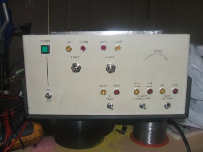
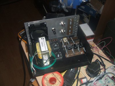
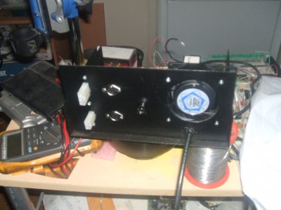
No its time to wire it up


No its time to wire it up


- Joined
- Apr 2, 2013
- Messages
- 230
Looks good  I must admit I was realy surprised at the power these little window motors have. Wasnt sure when I did mine but it works great, and with the PWM I can set it and then actually watch instead of cranking lol. Next step is to add one to the Z axis, which will be easy once I find a set of gears, that way I can swing the unit out a bit to quickly disengage for hand cranking. Got all my bits to do it, just need to hunt down some small gears, maybe 2-3" or so
Nice job. What RPM range are you getting? What is the ratio of the 2 gears? 12vdc I assume.
From memory I used a ratio of something like 6 to 26 teeth sprockets. Speed is zero to about 150 rpm. Power supply is an old 12 volt lap top computer pack . Speed control is a standard PWM ex Ebay (Hongkong supplier v. cheap).
It all works like a charm.
DavidL
I also used a 12 pt socket as a engage/disengage clutch for my power feed. The window lift motor has plenty of power for G0619 mill.
View attachment 53913View attachment 53914View attachment 53915
Hi bpratl,
Very nice work! I just picked up a G0619 and am quite keen to build both X & Z axis power feeds with engaging/disengaging clutches. I really like you design so a couple quick question for you:
What is the interface between the bolt that the 12 point socket engages and the X axis leadscrew? I assume you might have milled the sides of the bolt to allow it to key into the insert port of the leadscrew?
I also would guess that this bolt is supported by a bearing in your additional custom end plate?
Cheers,
Hoji


