-
Welcome back Guest! Did you know you can mentor other members here at H-M? If not, please check out our Relaunch of Hobby Machinist Mentoring Program!
You are using an out of date browser. It may not display this or other websites correctly.
You should upgrade or use an alternative browser.
You should upgrade or use an alternative browser.
Volvo Amazon 1965 (Volvo 13134)
- Thread starter MrCrankyface
- Start date
- Joined
- Sep 28, 2013
- Messages
- 4,395
YAAAAY! I'm so happy you're working on this again 
- Joined
- Nov 7, 2019
- Messages
- 483
Hopefully I keep updating and don't lose track. 
Spent an hour or so the other day.
Started contemplating to move the motor back even further, having to remake my mounts etc but hopefully worthwhile.
Upsides for moving motor back is: lower center of gravity, more equal weight distribution(front/rear), more space for cooler/intercooler up front.
Previously I chickened out, thinking it'd cramp the driving compartment too much.
Now I however placed a seat in the car roughly how/where I want it and hung up the original pedals, at least it feels like there should be enough space. I would also like to change to rack/pinion steering so with the move I should have more space available.
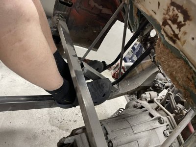
To plan my next move I checked the other side for the same repair as I just did, seeing as the 'rust removals' are fairly similar.
One thing that haven't struck me before, or I've forgotten, is that the left side is just a flat sheet, someone has done a real ****ty repair.
This makes a very big difference in strength and rigidity so needs to be fixed.
A replacement piece of good quality was pretty cheap so I've actually ordered one of those to save a lot of work.
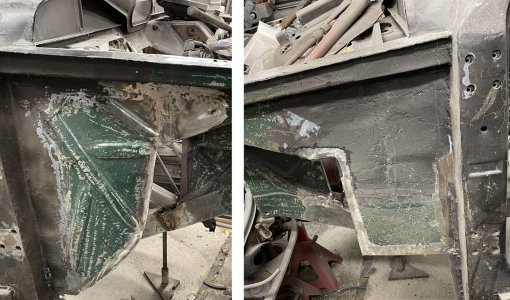
When checking what I needed to repair around the wheel well it struck me how incredibly crooked this cut is, to the point where I wondered if the car has sagged or if I was having a bad day when I cut it out. Went through old photos but couldn't find anything obvious. Jacked up the car at various points and this part doesn't seem to flex/move at all. Finally measured diagonally across the "hood" and it's very even as far as I can tell. Most likely just a bad cut to start with.
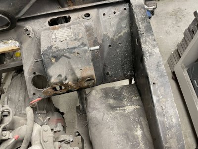
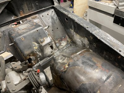
Spent a lot of time cleaning everything up for good welds, only to have a layer of tin run off into the weld, requiring grinding and rewelding...
Finally decided to move the motor in my next little session.
First I had to move the reinforcement bar out of the way by welding a new tube ontop of it and cutting the bottom out.
After that it was just a matter of loosening the current mounts, hooking up my engine hoist and wiggling things around.
The right side of the driveshaft gives you an idea of how much I could move it back, that mount was pretty much on the frame tube before.
I think this should be much better for the car overall.
Feels like I also managed to get the driveshaft down a bit lower which will make the interior less cramped.
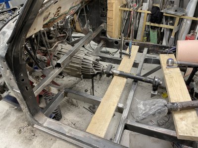
Fixing the engine mounts were a bit of a pain to be honest.
Since I had previously "finalized" this position, the mounts were fully welded and took a lot of work to cut apart and clean up so I didn't have to remake too much parts.
I did a very rough placement/weldment of the bottom mounts(against the subframe/front axle beam) and spent a tiny bit more time on the motor side mounts.
Just aiming for them to hold it in place securely and I can spend more time later to make them nice and pretty.
One thing that's obvious is that I have a ton of space now which should make things much easier in the future.
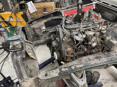

Spent an hour or so the other day.
Started contemplating to move the motor back even further, having to remake my mounts etc but hopefully worthwhile.
Upsides for moving motor back is: lower center of gravity, more equal weight distribution(front/rear), more space for cooler/intercooler up front.
Previously I chickened out, thinking it'd cramp the driving compartment too much.
Now I however placed a seat in the car roughly how/where I want it and hung up the original pedals, at least it feels like there should be enough space. I would also like to change to rack/pinion steering so with the move I should have more space available.

To plan my next move I checked the other side for the same repair as I just did, seeing as the 'rust removals' are fairly similar.
One thing that haven't struck me before, or I've forgotten, is that the left side is just a flat sheet, someone has done a real ****ty repair.
This makes a very big difference in strength and rigidity so needs to be fixed.
A replacement piece of good quality was pretty cheap so I've actually ordered one of those to save a lot of work.

When checking what I needed to repair around the wheel well it struck me how incredibly crooked this cut is, to the point where I wondered if the car has sagged or if I was having a bad day when I cut it out. Went through old photos but couldn't find anything obvious. Jacked up the car at various points and this part doesn't seem to flex/move at all. Finally measured diagonally across the "hood" and it's very even as far as I can tell. Most likely just a bad cut to start with.

Spent a lot of time cleaning everything up for good welds, only to have a layer of tin run off into the weld, requiring grinding and rewelding...


Finally decided to move the motor in my next little session.
First I had to move the reinforcement bar out of the way by welding a new tube ontop of it and cutting the bottom out.
After that it was just a matter of loosening the current mounts, hooking up my engine hoist and wiggling things around.
The right side of the driveshaft gives you an idea of how much I could move it back, that mount was pretty much on the frame tube before.
I think this should be much better for the car overall.
Feels like I also managed to get the driveshaft down a bit lower which will make the interior less cramped.

Fixing the engine mounts were a bit of a pain to be honest.
Since I had previously "finalized" this position, the mounts were fully welded and took a lot of work to cut apart and clean up so I didn't have to remake too much parts.
I did a very rough placement/weldment of the bottom mounts(against the subframe/front axle beam) and spent a tiny bit more time on the motor side mounts.
Just aiming for them to hold it in place securely and I can spend more time later to make them nice and pretty.
One thing that's obvious is that I have a ton of space now which should make things much easier in the future.

- Joined
- Nov 7, 2019
- Messages
- 483
Well, shortly after I managed to catch the flu and been out of order for a bit.
Got the replacement panel but due to how this car has been previously repaired it's not feasible to "install it as designed". I will instead cut out the parts I need/can install.
Just as a reminder of what I'm replacing, it's basically rust free, just the wrong shape.
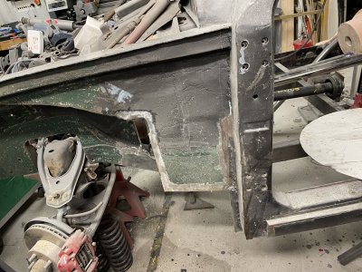
Tried to find the best places to cut, took a good while and a lot of grinding.
Might need to reinforce the inside later, not sure yet. Since old repairs have been layered on it's hard to tell how it's supposed to be.
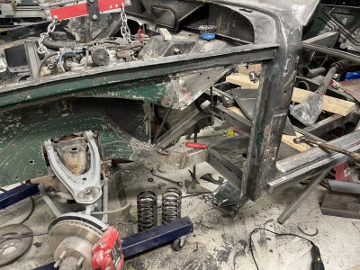
First layer of welds. Since it's impossible to get the surfaces properly cleaned I will have to grind this down a bit and reweld quite a few spots where contaminants got into the seam.
At least it feels like a big step forward in terms of getting it together.
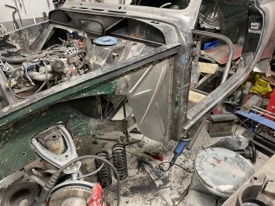
Next time I think I will mount a front wheel and see what I can do in terms of closing up the foot well.
Got the replacement panel but due to how this car has been previously repaired it's not feasible to "install it as designed". I will instead cut out the parts I need/can install.
Just as a reminder of what I'm replacing, it's basically rust free, just the wrong shape.

Tried to find the best places to cut, took a good while and a lot of grinding.
Might need to reinforce the inside later, not sure yet. Since old repairs have been layered on it's hard to tell how it's supposed to be.

First layer of welds. Since it's impossible to get the surfaces properly cleaned I will have to grind this down a bit and reweld quite a few spots where contaminants got into the seam.
At least it feels like a big step forward in terms of getting it together.

Next time I think I will mount a front wheel and see what I can do in terms of closing up the foot well.
- Joined
- Nov 7, 2019
- Messages
- 483
Mostly thinking here. Mounted a wheel up front.
Used a small jack underneath to adjust the A-arms level, which I'd like them to be for my ride height for minimal sideways movement as the suspension travels.
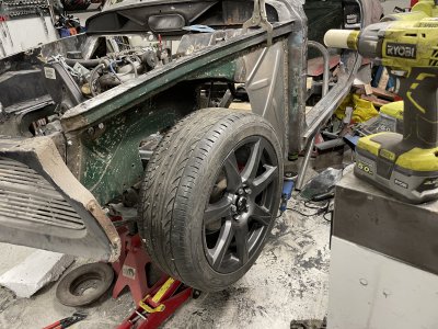
Space for making the foot well looks good. It's not going to be a ton of space but there doesn't need to be.
Should be fine to just close this up on both sides.
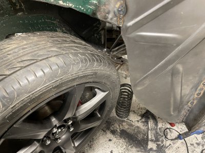
Turning is quite limited with the arms level, probably even more limited as the suspension bottoms out as that brings the tires even closer to the body.
Outwards I'm getting maybe ~35* and inwards ~25*, would make for a pretty garbage turning circle of ~12 meters.
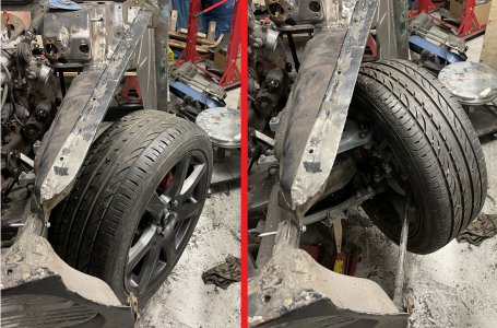
So I started thinking how I could improve this.
I know the rear axle I've installed is quite a bit wider than stock so I figure the front-end is also quite narrow in comparison.
Measuring from centerline of the car, just rough measurements to get an idea, the fronts sit at 74cm and the rear sits at 83cm. Ie I could move the fronts out almost 9cm on both sides.
Rough drawup in cad shows this should give me another 15-20 degrees of turning ie a vast improvement.
Next problem is how:
A. Spacers, easiest but for 9cm it's ridiculous idea and also major downsides(scrub radius, bearing load etc).
B. Extend A-arms.
+Should be make for a calmer suspension if I also draw up roll center and make sure it's still good.
+Somewhat easy to extend and reinforce.
-Not sure how 'legal' this is, ie will the inspector approve it. But considering that the rear suspension is entirely custom made and that's OK, I don't see why not if I reinforce it.
-Can mess with spring/damper ratio but car will also be a bit lighter than stock and never have 5 people + baggage in it.
C. Move A-arm mounts outwards and/or extend the front beam.
+Don't need to cut into A-arms.
+I retain the spring/damper ratio, assuming it was good to start with.
+Wider beam makes it easier to find rack and pinion to replace the old steering system.
-Massive pain to actually design and modify properly.
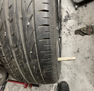
Currently I'm leaning towards modifying the A-arms. I could relatively easily take them out, cut them apart, make a jig and reweld them with further reinforcements. At least it's pretty nice to have the wheels back on, even if temporary. Makes it feel much more ready than it is.
A future problem is also the front wheel height. With the A-arms level I think the wheels will sit too low ie make the car too high. This is a difficult problem to sort out. Modifying the spindles is very difficult, I haven't found any replacement spindles that would work and make the car lower, modifying the front beam to move the arm joints further up is not really possible due to lack of space etc. There is a slight possibility of combining some wilwood spindles with a modified Volvo 140 hub or something like that but this is more of a rumor I've heard/read than fact.
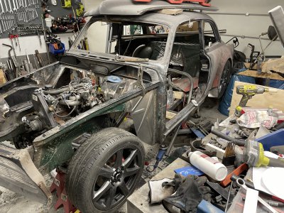
As a bonus, when I was investigating this problem, I also found the parallel I've been looking for.
Past me seem to have used it to space up the motor when making the new temporary mounts..
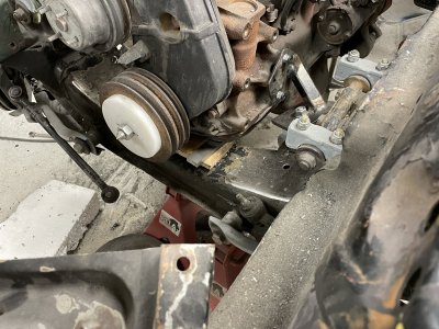
Used a small jack underneath to adjust the A-arms level, which I'd like them to be for my ride height for minimal sideways movement as the suspension travels.

Space for making the foot well looks good. It's not going to be a ton of space but there doesn't need to be.
Should be fine to just close this up on both sides.

Turning is quite limited with the arms level, probably even more limited as the suspension bottoms out as that brings the tires even closer to the body.
Outwards I'm getting maybe ~35* and inwards ~25*, would make for a pretty garbage turning circle of ~12 meters.

So I started thinking how I could improve this.
I know the rear axle I've installed is quite a bit wider than stock so I figure the front-end is also quite narrow in comparison.
Measuring from centerline of the car, just rough measurements to get an idea, the fronts sit at 74cm and the rear sits at 83cm. Ie I could move the fronts out almost 9cm on both sides.
Rough drawup in cad shows this should give me another 15-20 degrees of turning ie a vast improvement.
Next problem is how:
A. Spacers, easiest but for 9cm it's ridiculous idea and also major downsides(scrub radius, bearing load etc).
B. Extend A-arms.
+Should be make for a calmer suspension if I also draw up roll center and make sure it's still good.
+Somewhat easy to extend and reinforce.
-Not sure how 'legal' this is, ie will the inspector approve it. But considering that the rear suspension is entirely custom made and that's OK, I don't see why not if I reinforce it.
-Can mess with spring/damper ratio but car will also be a bit lighter than stock and never have 5 people + baggage in it.
C. Move A-arm mounts outwards and/or extend the front beam.
+Don't need to cut into A-arms.
+I retain the spring/damper ratio, assuming it was good to start with.
+Wider beam makes it easier to find rack and pinion to replace the old steering system.
-Massive pain to actually design and modify properly.

Currently I'm leaning towards modifying the A-arms. I could relatively easily take them out, cut them apart, make a jig and reweld them with further reinforcements. At least it's pretty nice to have the wheels back on, even if temporary. Makes it feel much more ready than it is.

A future problem is also the front wheel height. With the A-arms level I think the wheels will sit too low ie make the car too high. This is a difficult problem to sort out. Modifying the spindles is very difficult, I haven't found any replacement spindles that would work and make the car lower, modifying the front beam to move the arm joints further up is not really possible due to lack of space etc. There is a slight possibility of combining some wilwood spindles with a modified Volvo 140 hub or something like that but this is more of a rumor I've heard/read than fact.

As a bonus, when I was investigating this problem, I also found the parallel I've been looking for.
Past me seem to have used it to space up the motor when making the new temporary mounts..

- Joined
- Nov 7, 2019
- Messages
- 483
Mostly blabbering trying to think out loud.
I'm not ready to start chopping into the front suspension anytime soon and I feel more inclined to finish the firewall first.
I can't start working on the firewall before I finish the intersection between the new and old "frame" where the firewall used to be.
Furthermore I've been hesitant to spend more time on that section because I was unsure if my new frame was strong enough to pass inspection.
Originally the floor is supported by sheet metal bent up like a U-section of 80x80mm-ish. It's only partly supported by this since it's a unibody and not a body-on-frame vehicle so it's not straight comparison. Together with the floor and, a million spotwelds, this makes a somewhat light and stiff construction.
This is probably the best picture I have of the original setup.(Nov 2020, all photos in this post are fairly old)
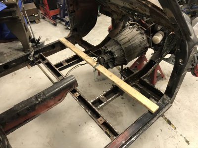
Since that entire 'frame' had massive amounts of rust, I removed it basically up to the white oil filter on the right in the picture above.
More from gut feeling than anything else, I ordered and started replacing it with 80x40x3mm tubing, I felt certain this would be strong enough but no real data to prove it so this has been something I've kept coming back to and feeling unsure about.
The new "frame" basically copies the old and then adds some extras like the support towards the backseat "beam" and much more solid joints etc.
This is to make sure I don't stray too far from the original design(which could push me into "new vehicle" instead of "modified vehicle" category) whilst still making sure I have plenty to work with for suspension mounts, floor etc.
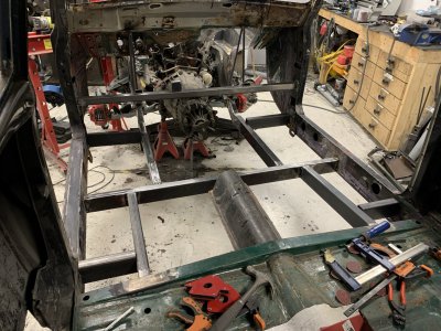
So the real difference here is 80x80x2 U-beams compared to my 80x40x3 tubing.
The U-beams are/were bent sheet metal and the tubing is decent grade steel(S335J2H).
Comparing data the old had slightly lower E-modulus, almost half the yield strength and of course a lot lower cross-sectional area.
Doing the calculations on this it turns out the new 80x40x3 tubing is ~6% stronger in their weak direction which is the one I was concerned about.
Seeing that it's actually stronger and knowing it's further reinforced than the old one makes me feel much safer and confident about this whole part of the project.
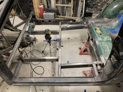
So what I'm going to tackle now is this section(view is from the front right wheel).
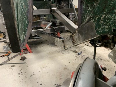
This was a bit of a "let's just get it together" solution. I think I will cut the tubing further down the edge and make a much smoother/milder transition. I have plenty of extra tubing so I can cut out sections and weld in a new top and not have to fill the gaps with weld.
Once the transition is more smooth, fully welded and blended back down, I will weld on some longer strips along the bottom and sides to 'bridge' the weld joints. Possibly overkill but doesn't hurt on such a vital location.
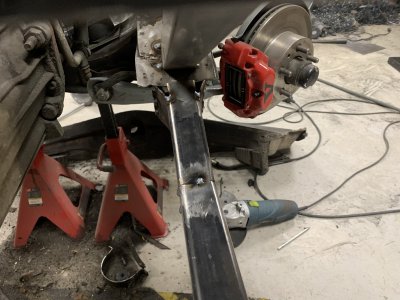
I'm not ready to start chopping into the front suspension anytime soon and I feel more inclined to finish the firewall first.
I can't start working on the firewall before I finish the intersection between the new and old "frame" where the firewall used to be.
Furthermore I've been hesitant to spend more time on that section because I was unsure if my new frame was strong enough to pass inspection.
Originally the floor is supported by sheet metal bent up like a U-section of 80x80mm-ish. It's only partly supported by this since it's a unibody and not a body-on-frame vehicle so it's not straight comparison. Together with the floor and, a million spotwelds, this makes a somewhat light and stiff construction.
This is probably the best picture I have of the original setup.(Nov 2020, all photos in this post are fairly old)

Since that entire 'frame' had massive amounts of rust, I removed it basically up to the white oil filter on the right in the picture above.
More from gut feeling than anything else, I ordered and started replacing it with 80x40x3mm tubing, I felt certain this would be strong enough but no real data to prove it so this has been something I've kept coming back to and feeling unsure about.
The new "frame" basically copies the old and then adds some extras like the support towards the backseat "beam" and much more solid joints etc.
This is to make sure I don't stray too far from the original design(which could push me into "new vehicle" instead of "modified vehicle" category) whilst still making sure I have plenty to work with for suspension mounts, floor etc.

So the real difference here is 80x80x2 U-beams compared to my 80x40x3 tubing.
The U-beams are/were bent sheet metal and the tubing is decent grade steel(S335J2H).
Comparing data the old had slightly lower E-modulus, almost half the yield strength and of course a lot lower cross-sectional area.
Doing the calculations on this it turns out the new 80x40x3 tubing is ~6% stronger in their weak direction which is the one I was concerned about.
Seeing that it's actually stronger and knowing it's further reinforced than the old one makes me feel much safer and confident about this whole part of the project.

So what I'm going to tackle now is this section(view is from the front right wheel).

This was a bit of a "let's just get it together" solution. I think I will cut the tubing further down the edge and make a much smoother/milder transition. I have plenty of extra tubing so I can cut out sections and weld in a new top and not have to fill the gaps with weld.
Once the transition is more smooth, fully welded and blended back down, I will weld on some longer strips along the bottom and sides to 'bridge' the weld joints. Possibly overkill but doesn't hurt on such a vital location.

- Joined
- Nov 7, 2019
- Messages
- 483
Sure took a lot longer than I expected. At least 4 hours of work here.
Cut some new lengths of tubing and used a slitting saw to open them up.
A parallel and some precision angles made it quick to setup for each piece.
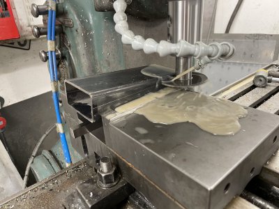
End up with 4 pieces that when assembled should be 40mm in one end and 70(apparently not 80) in the other end.
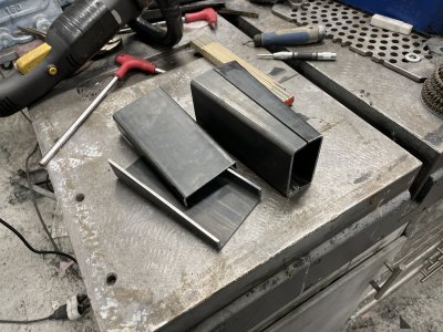
Lots of welding and blending later. Helped quite a lot welding these on the bench, easy to check for full penetration etc.
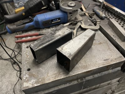
Cut the old piece out, would've been perfect for a sawszall but I converted mine to a power scraper.
Manage to get at some of it with the angle grinder and the rest was hacksaw. Cleaned it up afterwards and beveled the edges etc.
Before I cut it out, I added an extra vertical support at the frame intersection.
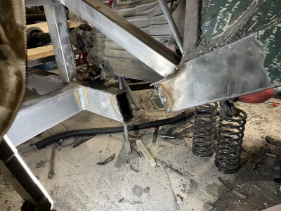
Finally new piece mostly welded in. Still need to grind the tops down a bit and check if I created any gaps etc.
Also need to shape it a bit since the frame it connects to was 70x70 and not 80x80.
Old "frame" also needs to be shaped slightly to connect nicely, I think I will bend the edges up and ramp them down to meet the new frame.
Unfortunately this issue didn't cross my mind despite starting this session with realizing the beam was 70mm wide and not 80.
Then I need to reinforce, cut, blend, shape etc on the left side as well but my energy was running low and I didn't want to start doing stupid mistakes/shortcuts.
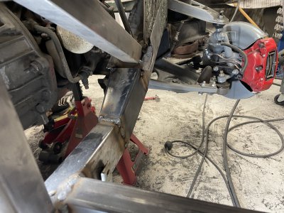
Cut some new lengths of tubing and used a slitting saw to open them up.
A parallel and some precision angles made it quick to setup for each piece.

End up with 4 pieces that when assembled should be 40mm in one end and 70(apparently not 80) in the other end.

Lots of welding and blending later. Helped quite a lot welding these on the bench, easy to check for full penetration etc.

Cut the old piece out, would've been perfect for a sawszall but I converted mine to a power scraper.

Manage to get at some of it with the angle grinder and the rest was hacksaw. Cleaned it up afterwards and beveled the edges etc.
Before I cut it out, I added an extra vertical support at the frame intersection.

Finally new piece mostly welded in. Still need to grind the tops down a bit and check if I created any gaps etc.
Also need to shape it a bit since the frame it connects to was 70x70 and not 80x80.
Old "frame" also needs to be shaped slightly to connect nicely, I think I will bend the edges up and ramp them down to meet the new frame.
Unfortunately this issue didn't cross my mind despite starting this session with realizing the beam was 70mm wide and not 80.

Then I need to reinforce, cut, blend, shape etc on the left side as well but my energy was running low and I didn't want to start doing stupid mistakes/shortcuts.

- Joined
- Jan 2, 2019
- Messages
- 7,145
Are you putting a roll cage into this car? If so that should stiffen the whole thing up quite a bit.
It’s been a while since I was reading my suspension books but I’d be inclined to leave the a-arms alone and move the mounting points outboard. If you can get Willwood racing components that will work that would be probably the better solution.
I assume this car will see some track use. If that’s the case it would be advisable to review your local sanctioning bodies rule book to get an idea of what would be required if you end up wanting to enter races at some point.
In either case I’ll recommend Carroll Smiths books carrollsmith.com you won’t go wrong following his wisdom on car preparation.
John
- Joined
- Nov 7, 2019
- Messages
- 483
Thanks for the recommendation, will look into it.
Before I do anything to the front suspension I will make sure to draw it up in CAD and check how it's setup from the factory regarding roll centers, camber gain etc. I've heard people complaining that the stock amazon is somewhat bad in their geometry so I'm still entertaining the idea of trying to fix it.
AFAIK both some corvette and mustang2 front beams can be modified to fit but seems more fun to make the original stuff work better than relying on someone elses work. I guess this is why my projects take forever since I want to do everything myself.
I don't see this ever being on a track as I'd be way too scared of breaking it with so much work into it.
It will have a rollcage that's specced for track use though, mostly because then you know it's good quality.
My thinking there is both the added stiffness, crash protection and should help me get the car through inspection with more horsepower.
Managed to get into the garage again, real productive.
Did the same operation to the other side and blended down the welds on both sides.
Easy in theory but chopping the old piece out and cleaning the ends off took almost an hour, furthermore very dirty/dusty work and uncomfortable working positions.
Really happy with how it's coming out tho, especially now with the old frame reshaped a bit.
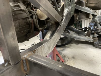
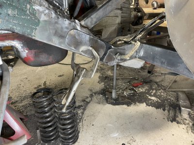
Something I've seen done on pickups with extended frames is welding plates over where it's been extended.
Also doesn't hurt to make sure the joints are as strong and spread out as possible, especially since the old and new frame are a bit different in thickness.
Did two extremely quick mock-up pieces but I think want one solid plate that goes across both joints, with a bunch of holes so it can be welded both along the perimeter and a couple of places "inside" the perimeter.
Before I do anything to the front suspension I will make sure to draw it up in CAD and check how it's setup from the factory regarding roll centers, camber gain etc. I've heard people complaining that the stock amazon is somewhat bad in their geometry so I'm still entertaining the idea of trying to fix it.
AFAIK both some corvette and mustang2 front beams can be modified to fit but seems more fun to make the original stuff work better than relying on someone elses work. I guess this is why my projects take forever since I want to do everything myself.

I don't see this ever being on a track as I'd be way too scared of breaking it with so much work into it.

It will have a rollcage that's specced for track use though, mostly because then you know it's good quality.
My thinking there is both the added stiffness, crash protection and should help me get the car through inspection with more horsepower.
Managed to get into the garage again, real productive.
Did the same operation to the other side and blended down the welds on both sides.
Easy in theory but chopping the old piece out and cleaning the ends off took almost an hour, furthermore very dirty/dusty work and uncomfortable working positions.

Really happy with how it's coming out tho, especially now with the old frame reshaped a bit.

Something I've seen done on pickups with extended frames is welding plates over where it's been extended.
Also doesn't hurt to make sure the joints are as strong and spread out as possible, especially since the old and new frame are a bit different in thickness.
Did two extremely quick mock-up pieces but I think want one solid plate that goes across both joints, with a bunch of holes so it can be welded both along the perimeter and a couple of places "inside" the perimeter.

- Joined
- Nov 7, 2019
- Messages
- 483
Cut together another video of the project.
This goes through some of the process of making the upper 3 link mount for the axle, pretty much what I showed on page 6.
This goes through some of the process of making the upper 3 link mount for the axle, pretty much what I showed on page 6.
