Volvo Amazon 1965 (Volvo 13134)

Well, figured out the linkage problem, I had just used the wrong hole on the upper axle mount...
Everything is good, checked suspension travel which is enough to fulfill the requirements. Might be tight to get springs and shocks in but that's a problem for future-me.

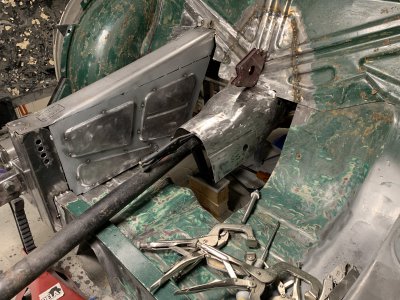
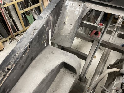
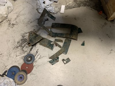
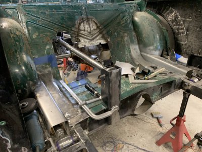
The weekends harvest.. Ended up needing to cut away quite a bit more to make the repair easier.
Panhard mount on the left was also removed, will fabricate a new one that sits where I want it.
IMG_4842.JPG

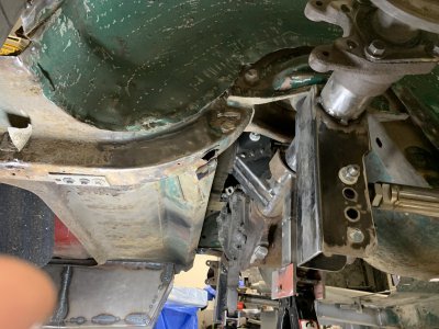
Of course the "frame" was in bad condition here as well.
Need to repair before I even think about making a new panhard mount, but my neck really does not like laying underneath the car right now so maybe this will have to wait until I can reinforce the car and turn it on it's side or something.
IMG_4821.JPG

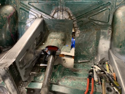
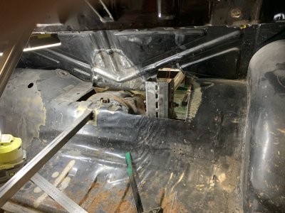
The view from the trunk.
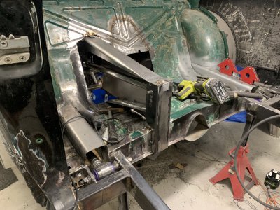
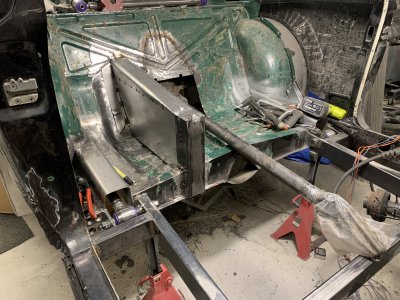
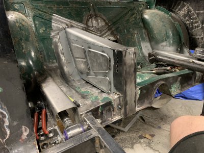
Quite a bit of floor needed to be removed to make space for the differential and upper mount.
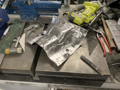
Will hammer some 2mm steel into shape to fill this in, with a folded down piece in the front that can get spotwelded to the new backseat wall.
The goal is to make it look as unmodified as possible where I can, just for esthetics.
IMG_4846.JPG

I think my next task will be trying to close this back up again.
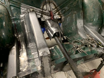
I will try to make a box of sorts around the upper link, down to the floor/seat area and then reinforce the backwall with an extra brace.
Should make the front mount strong enough and spread any load from it.
Combined with it will be a new driveshaft tunnel which should, hopefully, finish off the sheet work in the backseat area.
IMG_4838.JPG
 
Well this was a painful experience, it's like trying to finish a puzzle without knowing what it's supposed to end up like.
I've had this tacked and torn apart so many times by now but I think this is the way forward.
Initially wanted to beadroll the sideplates for strength but I don't have space to do it inwards and I don't want them outwards.
I think the interior brace will suffice though.
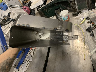
The idea is that this "inner volume" will be sealed off and essentially be the exterior of the car, the small area underneath will need to have some kind of opening I think, feels weird to have a closed off "dead space" but we'll see what I do.
IMG_4900.JPG


Ridiculous amount of time spent with little visual progress.
Lots of cutting, welding and grinding to get things into shape.
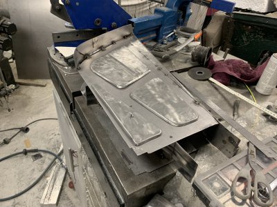
The "standing sheets" have been profiled in the rear to match the backseat wall and then a filler piece that took ages to make.
I wanted a perfect fit between the car and this part, without having to weld and hammer it into place, trying to up my game here in terms of fitment.
IMG_4901.JPG

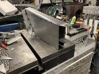
The entire piece comes out relatively easily and is still only loosely tacked together.
Will be much easier finishing it outside of the car and then welding it into place.
Not sure how I'm going to get to all the places I need to weld and also paint later on when it goes into the car but that's a future problem...
IMG_4903.JPG

Quick view of the inside.
IMG_4904.JPG

Next challenge is to start closing off the area around the differential housing.
 
I lied apparently, no differential work today. :grin:
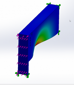
Got a comment on another forum, questioning whether the "tunnel" would provide enough strength to not buckle under heavy acceleration(torque from the rear axle wants to pull the top link backwards hence also wants to compress/buckle the tunnel)

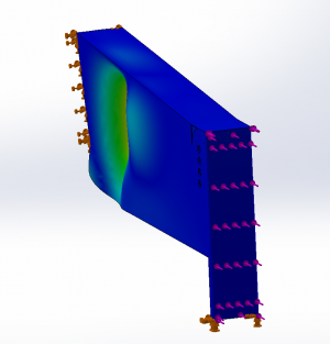
Did some quick simulations to get a feel for it, using the engines top torque value, multiplied by 1st gear and differential ratio, converted to force using the height/lever distance of the link mounts.
No reinforcement would lead to critical failure right in the middle.
1_noreinforcement.png

Welded to the floor and the internal reinforcement as in the previous posts photos will buckle in the "empty" area behind the reinforcement...
Definitely not where I want the the force to gather and really changed my mind about adding some shape to the sides.
2_internalbrace.png

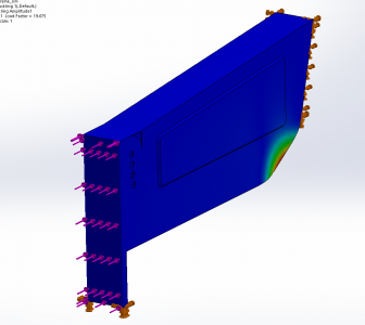
Final sim with just some shape beadrolled outwards into the side, massive difference and force is now in an unsupported corner, that IRL will get welded together with the car anyway.
The take away here is that even a small extruded shape makes a massive difference in strength when compared to a flat sheet.
3_morebraces.png

This leaves me a few different options.
1. Cut it apart and beadroll the sides
2. Beadroll the shapes separately and cut into the sides then buttweld everything
3. Beadroll the shapes separately but just weld them onto the sides.

1 feels like too much wasted work, and 3 is stronger than 2 whilst also being less work.
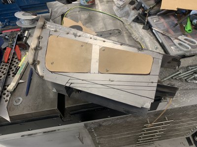
For once I actually drew things up "IRL" and cut out templates, pretty relaxing work to be honest.
IMG_4907.JPG

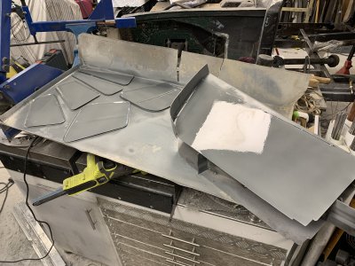
I used the templates to transfer the shape and cut it out of steel.
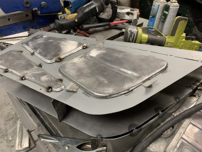
I then ran the edge in my bead roller to fold it down and get some height out of it.
Funnily enough the electronics broke "mid-project" and it now runs 100% speed as soon as you turn it on, which made it REALLY difficult to keep things in line. :grin::grin::grin:
Caused some oil-canning in the larger part but managed to fix most of it so it doesn't add tension to the assembly.
IMG_4908.JPG
 
Really on a roll lately.
Cleaned the panels off with acetone, primed/rustprotected the areas I can't reach later and tacked things together.
IMG_4911.JPG

I did raise the panels up with shims when tacking them.
Even tho it's fairly thin material I see no downside to making sure I get a deeper penetration since I'm going to grind some of it down again.
IMG_4913.JPG

Actually looks semidecent sitting in the car again.
IMG_4917.JPG

So on to the next problem.
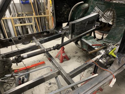
I need a rough understanding of where the driveshaft is going to sit to make further progress with the sheet stuff.
But apparently I have the wrong driveshaft so it doesn't meet up with the gearbox I have...
Went ahead and shortened it anyway, never done something like that before so was a good excercise.
Need to order the correct one but this will at least give me an idea of what I need to cover.
IMG_4924.JPG
 
Tiny update, I've noticed it keeps my motivation up to celebrate the small progresses and not only see the large milestones.

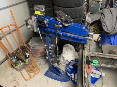
I've properly repaired and upgraded my beadrolling machine.
Before it broke, it had a pedal to control the speed but no option to reverse it.
Lack of experience made me design the control system like that, but when actually using it, I quickly realized you REALLY want to be able to reverse it.
Sometimes you want to stop in the middle of a feature and back out, sometimes you need to feed things in from the other end and so on.
Lesson learnt and not only did I replace the electronics with something that regulates much smoother, I also added a switch for changing direction.

I thought it could be fun to reuse some of the old sheet material and that it would also save some time.
Well, it was fun at least, took a ton of time. :grin:
IMG_4930.JPG

Just removing unwanted parts(reinforcements on the back that'd be in the way etc) and sanding it clean probably took around an hour.
IMG_4931.JPG

Tons of hammering, wheeling and beading later.
Rough steps:
-Managed to reverse the shape, what was previously spreading out sideways now goes downward.
Tons of hammering to force it over, then wheeling to smooth it.
-Spent some time wheeling any flat surfaces to make them slightly crowned, really helps them keep their shape and make a stronger product.
-Experimenting with beadrolling in that edge along the side to make it more visually appealing.
-Plenty of test-fitting during the entire process, and slowly removing more and more "waste" to reduce the overlap between pieces.
Still need to trim the sides to follow the "rear seat wall" and then I can start making filler pieces to the sides before moving forwards through the car.
IMG_4932.JPGIMG_4934.JPG

Been looking everywhere for a new driveshaft part but literally no one wants to sell just the "front piece" I need so ended up having to purchase another "complete kit"... The rear part of these are the exact same but I guess it's good to have a spare.
 
@MrCrankyface ,

Could you share some details of your bead roller motor and controller?

I recently picked-up a an old bead roller that only has a hand crank. There's no way I could steer the workpiece and crank the tool at the same time.
I have also spent more on dies then I did on the machine.

Did you build the new controller yourself?
How fine is the foot-pedal speed control?

Thanks,
Brian
Last controller I built myself and was not happy with.
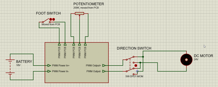
Current is basically this: PWM controller
Bought it on amazon a while back dirt-cheap but can't find it there currently, any PWM controller should work.
The potentiometer has 5 legs, 2 are acting as an on/off switch(to give a true 0%) and the three remaining are just as a regular potentiometer.
It's not specified to handle the 18+V DC I'm supplying it with but so far no problems, might want to get something with a better rating though to make it more reliable.
Using it because I had it at hand when my diy controller broke(transistor stuck closed).

The motor is originally from a height-adjustable desk, there's no real specifications on it so not sure what it's rated for besides 24V DC.
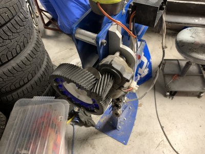
3D-printed some big gears to gear it down further than it's own internal worm-drive.
IMG_4960.JPG

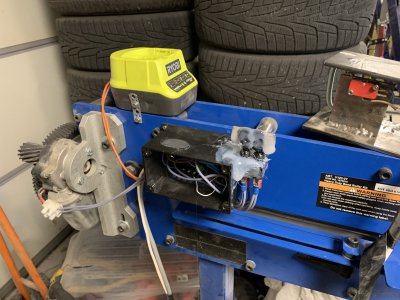
Motor wires goes to the sloppily glued-on switch to the right(forward/backwards switch) and then to the PWM board which gets fed by the battery holder ontop.
The board originally had the potentiometer mounted directly on it but I've moved it to my DIY pedal.
IMG_4959.JPG

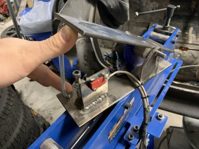
Spring is not strictly neccessary but makes sure it can't turn on by accident if the pedal falls over.
The on/off function of the potentiometer has been replaced with the microswitch, feels safer that way, more reliable shutoff.
Potentiometer is geared up to reduce pedal travel a bit, I think it has something like 270 degrees of travel, my ankle doesn't rotate that far :grin:
IMG_4958.JPG

Everything is just thrown together from scrap and whatever I had available, hence the double cables and "ghetto-diy" look.
It was more important to get it working than making it pretty. :grin:
IMG_4956.JPG

I would definitely recommend securing the motor better if you do something similar, under heavy load the gears want to push apart and I often get skipping.
Not a problem with regular sheet metal but if you try to do more extreme shapes or thicker pieces it's annoying.

Hopefully this makes some sense.
oKNwech.png

This setup has very fine control, the speed is fairly constant unless you roll into a much heavier resistance(trying to pass over a bead going a different direction for example) at which point you can just give it some more pedal etc. Easy to stay in control.
This machine came with a handcrank from the start but I didn't even try using it, you need both hands even on smaller pieces to hold and steer.
 
Last edited:
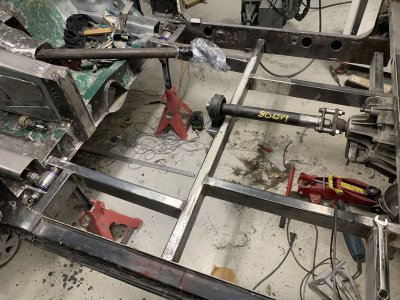
Figured I'd finish the driveshaft stuff first so I'm sure where the tunnel needs to be.
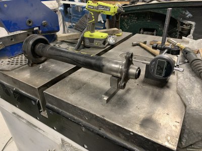
Got the "new" driveshaft, cut it apart, shortened and rewelded it.
It's pressfit quite a bit into the tube which is good in the sense that it's a very stable fit, and bad in the sense that it's pretty much not adjustable at all.
Biggest difference from "highest to lowest" is around 0.08mm, maybe that's good but should be improveable.
Unfortunately didn't check how good/bad it was before I cut it apart.
IMG_4984.JPG


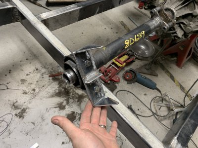
Next it's time for the support bearing.
I made some "precision spacers" and bolted the hardy-triangles together, this forces the shaft to be perfectly in line with the motor which greatly helps when trying to place the mount for it.
I threw some 4mm plates(cutouts from the rectangular tubing the frame is made out of) together to form a mount.
IMG_4993.JPG

For 2-3 hours of work I think it came out somewhat decent considering that it's 4 seperate pieces of plate, which were all way out of flat.
Welded everything on the bench and this will then get welded to the frame.
Currently I've just marked out on the frame where I need to remove the mill scale, won't weld this in before I can mount the hardy-rubber thing incase it's thickness differs from my spacers.
My mounting plate does have slots for adjustability but they're not very long so it's important to get it in the ballpark.
IMG_4992.JPG
 
It's frankly absurd how time just flies. Been a lot the last year and then some. Since the car requires a lot of thought and creativity I have continuously pushed it forward, trying to finish "what's urgent" and then resume the car later. I think I'm starting to realize that "later" will never come, so either I start trying to move forward or it will never progress.

So my new tactic here is to spend a few hours per week, just on anything on the car, and spend part of that time to document what I'm doing so I can more easily resume what I was thinking "last week".

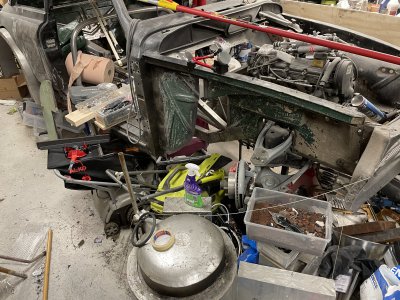
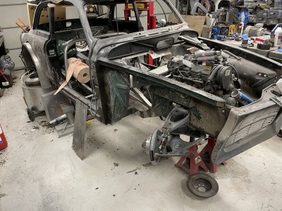
First challenge is just getting to the car... Took a good while just to move, sort and clean everything out of the way.
IMG_8143.JPG

MUCH more motivating to work on it! Last thing I worked on, over a year ago, was the driveshaft. That just feels like too much of an ordeal to get into at the moment so I will instead aim for lower hanging fruit, replacing the steel I cut out in the front.
Pretty much all of this was heavily rusted, a lot of it sandwich rust which is impossible to get to properly hence why I just cut it out.
IMG_8145.JPG

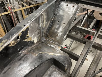
Further more, these plates joined together downwards, making a sharp edge towards the wheel well, not ideal when you're changing to much larger wheels. :grin:
IMG_8146.JPG

So what I got done today besides the cleaning, is welding these plates in.
Way more work than it seems, a lot of plaster, old shoddy repairs etc forced me to weld, grind, weld, grind, weld grind for quite a while to clean things out.
I will try to be less OCD when doing these short runs so I can just get things welded up and worry about blending it later, maybe when the car is solid and on a rotisserie.
Not gonna lie, feels really good despite being such small progress.
IMG_8148.JPG
 
Back
Top