Volvo Amazon 1965 (Volvo 13134)

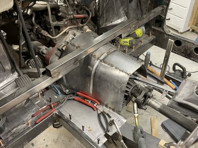
Well, the other side went a lot faster.
Roughly 3 hours to get this maybe 90% done compared to 4-5 full evenings for the first side.
IMG_8609.jpeg

Fit against the buck is similar as on the first side. Mostly just need to adjust some small bits so both sides are a bit more symmetrical and maybe bead some details into this second side so it’s more interesting.
IMG_8608.jpeg
 
Random little break to reorganize the garage and help out a friend with his car.
Long story short:
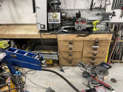
-Garage is chaotic and dirty. Bunch of drawers have over time become extremely disorganized.
-Friend discovered a bunch of rust above the rear subframe and the subframe itself is also in poor condition, on his fairly nice BMW, quite a big project with removing exhaust system, subframe, disassembling it etc. Took a surprising amount of attention and energy away from my volvo.

Regarding the first point. I made this bench ~7 years ago and it's definitely accumulated a fair amount of dirt over time as it's all untreated wood.
In the photo I've already sanded everything with 40 grit paper, the 'dust' coming off was oily enough to use like a loose clay. :grin:
IMG_8713.JPG

Since I had already started disassembling/removing stuff I just kept going, pulling out all the drawers etc.
IMG_8716.JPG

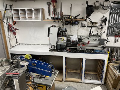
"Final" product.
-Everything is painted white(to make the room brighter, will definitely get dirty fast but still a mile better than plain wood.
-Built/painted sorting box holder to the left to both get rid of some sheet material I had and to be able to pull out a single box instead of rearranging the entire stack everytime I need something. Still need to label the boxes so it's easy to see which one to pull out.
-Replaced the drawer knobs with proper handles, much nicer to grip and you don't get stuck on them if you brush up against them.
-Added a proper shelf to the right of the compressor. Before the miter saw was stacked on the table saw etc, again a situation where you had to take everything out everytime you wanted one of the tools = inefficient and annoying.
-Used latex sealant around the entire drip tray of the lathe, should both reduce resonance and avoid small items/dirt getting in underneath and collecting.
-Reshaped all drawer fronts to have a nice chamfer.
-Moved the black allen keys over to match the "new" lathe position, these were far left before(where lathe used to be) and super annoying to go get.
-Furthermore all drawers have been emptied and reorganized so each is of the same category ie top is drills, second is tap/thread related, third is sanding related, fourth is grinding related and so on. Still need to label these up.
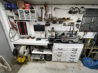
Still plenty of stuff to clean up and sort in here but it's a work in progress, basically everything laying loose needs to find a home.
IMG_8790.JPG

It is HOWEVER good enough and I've reduced the 'garage clutter' enough that I can resume work on the volvo! :grin:
Quite a bit of work that's hard to show to get to this point.
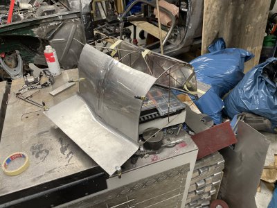
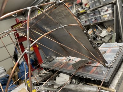
The wire buck wasn't serving it's purpose anymore as it's become too beat up and crooked, should've made it sturdier and spent more time trying to make it symmetrical/smooth.
Basically this made it very difficult to judge how symmetrical the pieces were and keep all shapes in order.
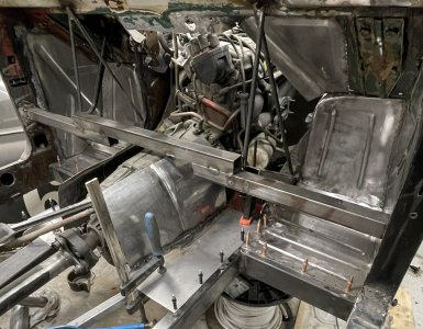
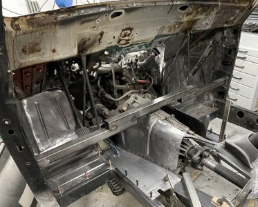
I marked some important measurements up on a sheet of plywood(transfered from buck) and screwed these parts onto the plywood so the "floor" part was flat.
After that it was much easier to judge what needed to be adjusted and so on, some rough adjustments later I could start drilling both sheet and car to cleco it in place.
I've added temporary supports underneath to make sure the sheet is still flat in the car and wooden blocks have been added to the gearbox to keep the proper distance from it.
Next step is to make some kind of symmetry line and do some "final" adjustments to the upper edge before I can start making the piece that will connect the two sides.
IMG_8786.JPGIMG_8788.JPG
 
Manage to slap the tunnel together.
I'm probably going to use some points in the car to measure from and put some marks on the new pieces.
The whole reason for this is because the "openings of the tunnel" are not flat from all the work I've done and I'd really like to cut them flat/orthogonal to the floor to make the next parts easier to make/measure out.
I've added a bunch of clamped parts underneath to keep this supported so I think the best next step is to make the real brackets that will have the same function.
After the real brackets/supports are made I should probably keep moving forwards and finish the firewall before I keep making the tunnel towards the rear.
IMG_8798.JPG
 
Had to take a bit of a break to prioritize other things and let my elbows recover but I hope to be able to make some progress the coming 3 weeks.
Main aim is to finish the tunnel piece I've started making and at least close up the firewall, hopefully the entire floor.

Todays "mini project" was a piece behind the ignition of the motor, a bit of a handful for me since it needs to match up to both the curved tunnel, top of firewall and not intrude too much into the "ignition area", I try to keep a thought about future maintenance etc.
I pushed it down as much as I could in the bead roller but still found it a bit too tight of a fit between motor/firewall.
IMG_7557.JPEGIMG_7559.JPEG

So after a thorough hammering against a sandbag and then wheeling it, I have what seems to be much more comfortable amount of space.
Halfway through I realized it would be a lot easier to fit this piece if I could weld it to the tunnel, but the tunnel needs to come out for it's final steps ... Hence I need to completely finish the tunnel before I can resume on this piece.
IMG_7562.JPEGIMG_7561.JPEG
 
those compound curves are a real bear with sheet metal. Sometimes slicing, folding and rewelding can help, though it's alot more work.
 
Definitely! I try to avoid that technique because I'm so tired of welding and grinding.. :grin:

Currently I'm much more fond of using this hammer I made.
Cut the head off an old hammer and welded this tube onto the shaft.
The tube is then filled with sand so it acts like a dead blow hammer.
Final trick is that the "tips" are replaceable and 3D-printed so I can quickly try any weird shape I want.
Took me maybe 5-10 minutes of bashing for that last piece and then another 5 minutes rolling out the dents in the english wheel.
It definitely takes a toll on my elbows but much less work and cleaner than cutting, welding and grinding so at the moment it's my preferred method.
IMG_7563.JPEG
 
Took the tunnel out and bead-rolled the sides. I wanted to make a much more complex shape using a hammer form but figured some progress is better than another 6 week side-project.
I didn't pre-stretch and experimented with different wheel combos so I got both a lot of warping and varying quality on the beads.
Furthermore took some measurements on where to cut the tunnel at the rear since I've somehow managed to make one side longer.
IMG_7618.JPEGIMG_7619.JPEG

Next I cut off the excess at the rear, hammered/bent the floor part flat again and manipulated the beads quite a bit to make them more defined.
Fully welded everything so it's ready for blending.
IMG_7625.JPEGIMG_7624.JPEG

And finally blended down somewhat and given a quick surface brushing.
IMG_7626.JPEGIMG_7627.JPEG
 
"Installed" the tunnel and quickly realized I should probably do the transmission mount before I even consider welding the tunnel in.
IMG_7630.JPEG

The original frame had two reinforcements going towards the center like this, but they were not connected in the middle.
The idea I have is to have a tube like pictured but cut out/reinforced as to be slung under the gearbox a bit.
Whilst still being connected to both sides it should still support the floor and be much stronger.
IMG_7633.JPEG

But first I needed to figure out where and how I wanted to place my bushings.
Ridicilous slow progress when trying to do stuff like this, a lot of time is wasted on measuring, testing, going back and forth between test-fitting and milling/drilling etc.
Finally satisfied with the fit I added two flanges to set the bushings in.
They're tilted inwards and forwards so they don't need to purely act in shear.
IMG_7672.JPEGIMG_7674.JPEG

I started working on the crossbeam but got tired of the messy work.
Used a 2x4" piece of lumber to mark and make quick test cuts which I then transferred to this tube.
Still quite a bit to go on this before I can fit it on the car.
IMG_7677.JPEG
 
Last edited:
Back
Top