VN12 Spindle Project of 2013

Shopsweeper

Active User
H-M Lifetime Diamond Member
Joined
Oct 30, 2012
Messages
157
Many of you know about the drama surrounding my Van Norman 12 and the non-R8, non-5V spindle. (a previous owner tried a "garage conversion" to R8).

I am working with a local student to create a CAD file for me (us). I want this products of this effort to held in the public domain as a small token of my esteem toward many of you who have helped me directly and indirectly while learning about these old machines.

The goal is an Van Norman C Spindle (V5) measured drawing (CAD file) that would be a replacement for worn VN12 ball bearing spindles.
A sub-goal is to provide some idea of what shops (listed by name) might charge for work like this.
Another sub-goal is to do the same for roller brearing models (assuming they differ) and any other variants of the VN12 Spindle we identify.
Another sub-goal is to cook up a spec for an R8 spindle if anyone wants that (this should consist of different ID measurements only).

To this end I will be soliciting answers and advice in this thread (leaving my other thread to be specific to that one machine). My hope is that this thread be about more than once machine and that we can come up with BOTH Roller Bearing and Ball Bearing VN12 spindle specs (and any other VN12 spindle types that may exist).

I pledge to update this thread as progress occurs, and I will use it to ask for help as well. I am not a great machinist, but I am Project Manager by vocation. So I am addressing this challenge in a Project Management way.

Please note: No part of this project is intended as disrespect to [SIZE=-1]Repair Parts, Inc.[/SIZE] They have been a great resource to many VN owners and if they had a spindle to sell me I would buy one (maybe two) today. The simple fact is that my efforts to get RPI to release their out-of-patent drawings to a machine shop (of their choice) to quote me a part were not successful. I doubt that I am the first or the last customer to ask this of them. I simply feel that a community based effort can fill a hole that is not being met today by commerce alone.
 
Nice project. Some quick thoughts:

1) R8 has 1/16" less capacity, I believe: 9/16 vs 5/8. On this basis alone, I'd have no use
for it. Effectively, that cuts my choice of end mills.

2) Some thought must be made to process: start with hardened steel i.e. 4130 or heat treat.
Either greatly influences who/how it will be made.

3) a quill is the "most desired" feature; so it might be interesting to make the tradeoff
at design time: collet capacity vs quill.... or

4) "the holy grail"; and interchangeable "cartridge" design than can be tailored to either collet
or quill use.

Yeah, I know: I'm dreaming. But then I do industrial design work for a living. Getting the
"right" set of requirements can dramatically change your "end user market"!

FWIW.

--frankb

Many of you know about the drama surrounding my Van Norman 12 and the on-R8, non-5V spindle. (a previous owner tried a "garage conversion" to R8).... I simply feel that a community based effort can fill a hole that is not being met today by commerce alone.
 
FWIW i agree with Frank, and would recommend grinding the new spindles for 30 taper. size isnt much different in the diamter, in fact i think they are the same. but it will mill alot more. Let me know if you need some help on the CAD end, as i work with alibre (now geomagic!) and can find my ass with 2 hands... sometimes.

I do like the idea btw, and you have a host of knowledge on this forum!

 
Question 1: What should the offset be between the know dimensions (OD) of 5V toolholder and the ID of the spindle?

Another way to ask the same question: how tight should a spindle be on the collet?


Since my 5V is no longer 5V I can't simply measure it, but thanks to Cal and others I have specs on Van Norman C (5V).


I like the 30 Taper idea. 5V first in CAD, 5V first in production but after that, it should really only be a quick change in the CAD file.
 
...

I am working with a local student to create a CAD file for me (us). I want this products of this effort to held in the public domain ...

The goal is an Van Norman C Spindle (V5) measured drawing (CAD file) that would be a replacement for worn VN12 ball bearing spindles.

A sub-goal is to provide some idea of what shops (listed by name) might charge for work like this.

Another sub-goal is to do the same for roller brearing models (assuming they differ) and any other variants of the VN12 Spindle we identify.

Another sub-goal is to cook up a spec for an R8 spindle if anyone wants that (this should consist of different ID measurements only).
...
I like the idea.

Just to clarify, all Van Norman No. 12 spindles use tapered roller bearings; the older No. 12s had gearboxes that used ball bearings.

There were about 5 different cutter-heads used on No. 12s, including what I call the 12/16 cutter-head which was used on late model No. 12s and on the No. 16. (The No. 16 is the direct descendant of the No. 12 and uses the same basic gearbox.) I don't know to what extent the spindles were interchangeable among the various cutter-head castings. It's clear to me that Van Norman struggled with the problem of how to lock the ring gear to the spindle and tried several different approaches. All of the early heads used a single large key to drive the spindle. The 12/16 heads went to splines on the spindle and ring gear, and those machines also switched from key to spline drive in the ram gearboxes. Along the way, Van Norman also changed from lubricating the front bearing with grease to lubricating it with oil from the ring-gear reservoir.

I think it would be a good idea to take advantage of any advances in the design of later spindles that can be used on a spindle for an early model machine. A key constraint is going to be the ring gear. If minor modifications can be made to the cutter-head casting to allow a more universal spindle, then that would be the way to go. At this point I'm only aware of two ring gears: 12-633, used in the older No. 12s; and 16-1081, used in the 12/16 cutter-head. However, based on the 12-633 ring gear's part number, I'm pretty sure that there is an older version out there, with a part number in the low 200's.

I think that a good starting place is to get a good drawing of a spindle and the essential features of the mating ring gear. The drawing should be in a format that can be widely used. The .DXF format can be imported by most CAD packages. I use Draftsight, which is free. It's essentially an AutoCAD clone from Dassault Systèmes, the giant software company that owns SolidWorks and Catia:
http://www.3ds.com/products/draftsight/overview/

I have the spindle from a 1943 vintage, ball-bearing gearbox VN 12 (which should be part number 12-899) and one from a 1951 vintage VN 16 (part number 16-1079). Both are out of their cutter-heads where I can check dimensions, as needed.

Down the road we should develop a spreadsheet of the critical dimension of the various spindles and their mating ring gears. It would be good to include bearing and seal part numbers in the spreadsheet as well. Once you know the external dimensions of the spindle for your machine you are free to do what you like as far as the internal taper goes. Personally, I think that R-8 is a poor choice since it has no provision for drive dogs for an arbor. NMTB 30 taper might be an option, but I don't know if there's enough meat on the end of the spindle to allow it without making the spindle longer and changing the front bearing cap, etc.

Cal
 
I am glad to have some folks on board.

Cal, do you think that the old VN Part numbers will serve as a good enough naming convention for the Spindle + Ring gear?

I will plan on keeping track of these in pairs (Spindle+Ring Gear).

I got a rough sample file from my friend Trevor who is helping me digitize. It's not ready for prime time yet but a picture may help spark imaginations (since picture less threads can be worthless...). I can't upload right now but I will do so tonight.
 
...
Cal, do you think that the old VN Part numbers will serve as a good enough naming convention for the Spindle + Ring gear?
...
That's how I'd do it.

On the ring gears, you wouldn't need to try to model the teeth on the gear. A simple section of the gear showing the ID details plus OD, thickness, and perhaps the approximate slope of the bevel should be all that's needed. Several of the gears that I've looked at have a number on them; I think that it's the thickness of the gear, but I haven't verified that. If so, it's probably useful for setting up the mesh of the gears.

Cal
 
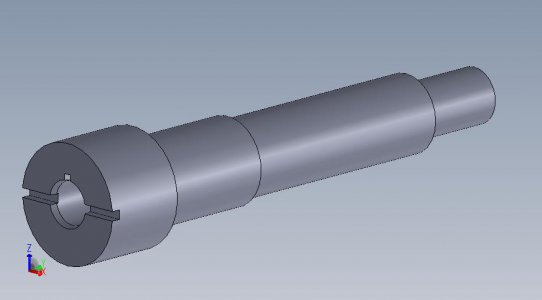
Here is a preview of our first deliverable: a 5V Spindle for my 12. I need to get measurements to the CAD Tech next week but he cooked this up based on an email of the part pic from the manual and a part diagram of a 5V collet.

Spindle Preview.jpg
 
Here is a preview of our first deliverable: a 5V Spindle for my 12. I need to get measurements to the CAD Tech next week but he cooked this up based on an email of the part pic from the manual and a part diagram of a 5V collet.
What CAD package is he using, if you know?

Does he have a background in mechanical design?

Cal
 
I THINK Solidworks, he told me but I am not sure.

This guy is a designer but his experience is more along the lines of injection molding pattern making. But he is energetic and hungry - he works cheap (as a favor to me, I am sure).

He is asking A LOT of questions that I cannot answer right now about measurements.

My cutter head is sitting in parts cleaning fluid. I wish I had an utrasonic large enough to hold the entire head.... I am OCD about cleaning and painting.

My day got derailed sanding and painting 6 Doublewide Vidmar cabinets (with heavy equipment shelves on bottom for tooling!).
 
Back
Top