VFD On Geared Head Lathe

Paul, I'm on the same page as you with the 10 hp rpc. At some point I will do that, but for now I won't miss the high spindle speeds. The vfd was powered with single phase 220. The 110v I mentioned was just an extension cord that he wired into the control panel to power everything but the motor ( and possibly the spindle brake....not sure about that). I think wiring up a vfd for this lathe is a little bit out of my league. Of course if a 10 hp unit comes down the pike I probably wont pass it up.:))

Chuck
 
I'm not familiar with this particular lathe, so I'm guessing here. I once used a Clausing lathe that would start the motor, and you would engage the spindle via a clutch. Does your lathe work that way?

We had a nearly identitical problem when our clutch wore out. The increased resistance makes the clutch slip, before the spindle gets to speed. Low speeds were no problem, due to the mechanical advantage. At medium speeds the clutch would slip when cutting.

If your lathe has a clutch, I would check this first.

-Cody
 
Cody, What your saying makes a lot of sense, but this machine doesn't have a clutch. It's either off or on. I really think I have a power issue...at least that's the avenue I'm going down until I prove myself wrong. Thanks for the input.

Chuck
 
Mr. Chuck;

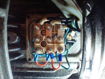
Your Polish lathe is wired for 480 v or high voltage. The picture of the jumpers in the pecker head gives it away. Change to the alternate arrangement per the label which will give you a "Y" connection in parallel. The motor has two windings, each capable of dropping 240 volts across them. Wired in parallel, side by side, they each drop 240 volts and you read the amperage of each doing so so it is twice the amperage of the high voltage connection. Wired in series, as they are now, they are connected end to end. With each dropping 240 v, 240 v + 240 v = 480 v.

You will also have to change the heaters in the magnetic starter as they will (or should be) only capable of carrying the 1/2 the amperage necessary for a 240 v connection. If you do not change them your starter will trip out due to overload when there is none. The heaters are the gizmos held in by two screws just above where the motor leads leaving the panel are connected to the overload block. They are spring loaded so when they jump out and it clicks, don't be alarmed! Look in the phone book for Square D, call the supplier and give them the rating of the motor, (3 kw) they should at least tell you where you may purchase them. If you have a CED (Consolidated Electrical Distributors) in your town I would start there. They are nation wide and the local guys at least are great. Just no guarantees that branch house handles the Sq "D" brand.

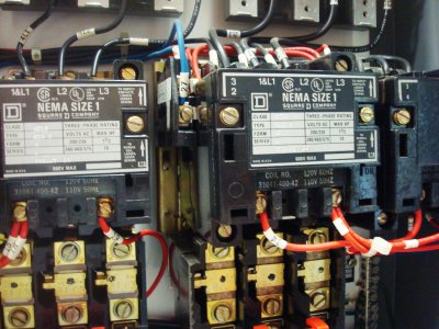
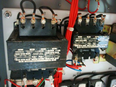
Nice control panel. The magnetic starter on the lower right with two contactors and only one overload block is the reversing starter for the lathe drive motor. I have no idea what the left hand starter is for, coolant pump maybe? Also check the control transformers for the proper connection for the voltage supplied. Control transformers may also be wired for 240 or 480 volts.

The largest VFD I am aware of that will operate on 240 v single phase is 7 1/2 hp. The largest on 120 v single phase is indeed 3 hp. But go to your industrial supplier and ask. They come out with new stuff almost daily and you have to keep up with it. Or at least I used to when I was in the biz! VFD's do have timers that allow you to program start up and shut down times to reduce and control inrush current. The terminology is usually "ramp up" and "ramp down times". This is where inductive breaking enters the picture, by injecting current spikes into the motor if needed to control the stopping time. Else it just slows the frequency to zero at the rate set. These spikes are what break down motors that are non inverter duty rated. This is why they are so touchy about guarantees unless your motor is rated for such use. And if it is an older motor, it is not.

A lathe starting with nothing in the chuck (no load condition) should start and run regardless of what gear they are in. If they don't, you have a problem, as you know! Motors are hard to start and may draw up to or over ten times the nameplate data, but only for a short time. A motor, electrically speaking, is a dead short. Until the rotor starts to turn, creating counter electromotive force, the resistance in the windings is virtually nil. The slip in a motor is how much the rotor lags behind the sine wave in a 3 phase sine wave. This slip is due to bearing resistance and physical weight of the rotor itself, and the load imposed upon the motor. The farther it lags, the more current it draws and the less efficient it becomes. This lag from synchronicity speed is also what causes heat and poor power factor which messes with your rpc also. Basically creating watt-less un-measurable current that shows its self as heat, harmonics and other undesirable electrical noises. Humming, buzzing, rattling, etcetera.

Are you glad you ask?


Edit---Check your RPC also for proper voltage hook up. An added thought!
 
Excellent information there and I'm sure that will help Chuck out a lot!

BTW: Just want to mention that you don't absolutely need to oversize a VFD. If you have a 1 HP motor, a 1HP rated VFD will work fine etc... There's nothing wrong with getting one oversized, it won't hurt anything but, it's not necessary unless you plan to really drive the motor hard on a very regular basis. In that case, the VFD might last a little longer since it's not being stressed to it's maximum output. The motor only uses up what it's capable of putting out when the situation calls for it.

It might be a different story with RPCs but I'm not familiar with them so someone else can possibly clarify.

Ray
 
Mr. Chuck;

Your Polish lathe is wired for 480 v or high voltage. The picture of the jumpers in the pecker head gives it away. Change to the alternate arrangement per the label which will give you a "Y" connection in parallel. The motor has two windings, each capable of dropping 240 volts across them. Wired in parallel, side by side, they each drop 240 volts and you read the amperage of each doing so so it is twice the amperage of the high voltage connection. Wired in series, as they are now, they are connected end to end. With each dropping 240 v, 240 v + 240 v = 480 v.

You will also have to change the heaters in the magnetic starter as they will (or should be) only capable of carrying the 1/2 the amperage necessary for a 240 v connection. If you do not change them your starter will trip out due to overload when there is none. The heaters are the gizmos held in by two screws just above where the motor leads leaving the panel are connected to the overload block. They are spring loaded so when they jump out and it clicks, don't be alarmed! Look in the phone book for Square D, call the supplier and give them the rating of the motor, (3 kw) they should at least tell you where you may purchase them. If you have a CED (Consolidated Electrical Distributors) in your town I would start there. They are nation wide and the local guys at least are great. Just no guarantees that branch house handles the Sq "D" brand.

Nice control panel. The magnetic starter on the lower right with two contactors and only one overload block is the reversing starter for the lathe drive motor. I have no idea what the left hand starter is for, coolant pump maybe? Also check the control transformers for the proper connection for the voltage supplied. Control transformers may also be wired for 240 or 480 volts.

The largest VFD I am aware of that will operate on 240 v single phase is 7 1/2 hp. The largest on 120 v single phase is indeed 3 hp. But go to your industrial supplier and ask. They come out with new stuff almost daily and you have to keep up with it. Or at least I used to when I was in the biz! VFD's do have timers that allow you to program start up and shut down times to reduce and control inrush current. The terminology is usually "ramp up" and "ramp down times". This is where inductive breaking enters the picture, by injecting current spikes into the motor if needed to control the stopping time. Else it just slows the frequency to zero at the rate set. These spikes are what break down motors that are non inverter duty rated. This is why they are so touchy about guarantees unless your motor is rated for such use. And if it is an older motor, it is not.

A lathe starting with nothing in the chuck (no load condition) should start and run regardless of what gear they are in. If they don't, you have a problem, as you know! Motors are hard to start and may draw up to or over ten times the nameplate data, but only for a short time. A motor, electrically speaking, is a dead short. Until the rotor starts to turn, creating counter electromotive force, the resistance in the windings is virtually nil. The slip in a motor is how much the rotor lags behind the sine wave in a 3 phase sine wave. This slip is due to bearing resistance and physical weight of the rotor itself, and the load imposed upon the motor. The farther it lags, the more current it draws and the less efficient it becomes. This lag from synchronicity speed is also what causes heat and poor power factor which messes with your rpc also. Basically creating watt-less un-measurable current that shows its self as heat, harmonics and other undesirable electrical noises. Humming, buzzing, rattling, etcetera.

Are you glad you ask?


Edit---Check your RPC also for proper voltage hook up. An added thought!


I'll have to look at this again. I had assured myself that it was wired correctly for 220v. The diagrams on the cover were confusing to me so I did a web search and compared the current wiring to the diagrams I found online. It looked right to me. Now as I think about it....when we changed the wiring and tried starting it, it just made a loud click and then nothing. If it has the wrong heaters in it, that would explain why it didn't work wired the other way. I really appreciate your explanation.

Chuck
 
Chuck,

I'm not all that familiar with RPCs but as far as VFDs go, there are none that I know of that power above 3HP when wired with single phase input. In other words, VFDs above 3 HP require three phase input.
Ray

That is the old way of thinking. There are lots of large single phase VFDs on the market these days - 10hp and beyond even if you have the amperage to supply them. They will cost you though. A 5hp rated 1ph in VFD will deliver the full 5hp. Here is a good one - SpeedStar:

http://www.driveswarehouse.com/p-2123-pc1-50.aspx
 
Thank You! I've been looking for a unit like that for a while and it eases my decision on the next lathe which has a 5HP motor.

Thank you!


Ray

That is the old way of thinking. There are lots of large single phase VFDs on the market these days - 10hp and beyond even if you have the amperage to supply them. They will cost you though. A 5hp rated 1ph in VFD will deliver the full 5hp. Here is a good one - SpeedStar:

http://www.driveswarehouse.com/p-2123-pc1-50.aspx
 
Ok....I took the cover back off the motor and rewired it the opposite way shown on the diagram. The thing that confused me is that the terminal block is upside down. Once I took off a wire and used U1 as a reference point the diagram made sense to me. It's wired the same way as every dual voltage motor I've dealt with. I put power to it (5hp rpc) and hit the lever for forward spindle rotation @ 630 rpm. The relays clicked in and out and the spindle jerked each time the relays clicked...then nothing. This is the same thing that happened when my friend wired it this way the first time he was trying to troubleshoot it. At that point he looked at everything in the control panel and said that it was all set up for low voltage and although it didn't make sense to him, he thought that european motors might be wired differently than anything he works with. So at that point he wire the motor the way it was originally and made plans to power it with a vfd to see if that would make it run at the higher rpm ranges. The vfd wouldn't power it either and that brings me up to where I am with it today. At this point he's convinced that there is something in the control panel that isn't right. I took more pics of everything and I'll try to put captions with them as I post them, but I've had problems doing that in the past.

I couldn't figure out how to add captions so here's how the pics go:

The first pic is how I rewired the motor. I switched the metal jumpers from the bottom to the top and added wire jumpers on the bottom to effectively link the the 3 wires together.

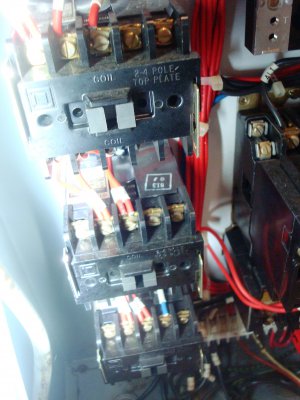
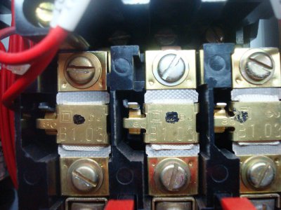
The second pic is the relays

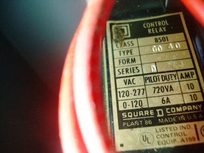
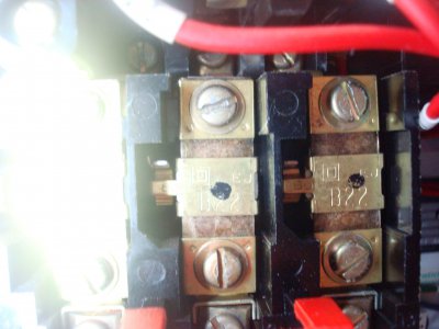
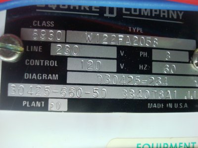
The 3rd pic is the tag on the relays

The 4th pic is the starters

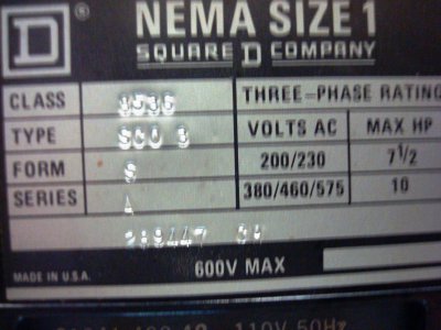
The 5th pic is the starter tag

The 6th pic is the heater

The 7th pic is the heater tag

The 8th pic is the transformers

The 9th pic is the panel tag

rewired.JPG Relays.JPG Relay tag.JPG starters.JPG starter tag 2.JPG heater.JPG heater 2.JPG trans.JPG Panel Tag.JPG
 
Chuck, Here are my initial thoughts.

Typically you only power the motor with a VFD - you do not have any contactors/relays or control circuits on the output side of the VFD. In fact it is not advisable to do that AT ALL. Try this. Wire the motor directly to the VFD T1,T2,T3 (or whatever the motor outputs are) and try power testing it only using controls on the VFD. You will do all your machine control from intelligent inputs/outputs on the VFD. You will use external switches to change input configuration settings on the VFD.

Also you said you had a 5hp and 7.5hp VFD. Are you using single phase in and are your VFDs rated for that? If your VFD is a 5hp 3 phase in VFD you typically derrate it by half. So that 7.5hp is not rated for 5hp single phase. It may work but you may error out the VFD under load. Hopefully it is sized and rated correctly. Guessing this was the case with the 7.5vfd not running fast enough.

Also in one of the pic specs it says control is 120V - that typically means your coils may be 120V. Your VFD is sending 120V to each side of the coil (two hots total) and not just one side and neutral to the other. Verify the coil type in each contactor. Again I would bypass all of these anyway.
 
Back
Top