Vfd for an old 3hp lathe

Only trying to help....

Many sizes, models, and quality of VFDs out there, and yes a lot of opinions about what these things should do and how they should perform. These conversations are tainted by the concept of a generic VFD and many different installations. So, for the most part, I went by the manufacturer's specs and instructions.

There are two main issues associated with wire size. 1) Is the load so large that the wire gets hot and causes a fire. 2) Is the wire so small that it supplies a smaller voltage to the load than the load wants to see causing the load (VFD or motor) to fail (similar to a brown out). In the end you get to decide what you want to do as long as it meets electrical code (or that no one ever finds out). The fuse size, and code to some extent, simply tries to prevent item 1, the fire problem.

This is the model I mentioned that I used for my PM1440GT (3HP 3Phase) conversion:
The 420 page manual is here: https://www.hitachi-iesa.com/sites/default/files/supportdocs/WJ200_Instruction_NT325X.pdf

Hitachi WJ200-022S Model:
Input voltage: S=Single-phase 200V class, if there is an extra F at the end it stands for the keypad type
Applicable motor capacity in kW: 022 = 2.2kW

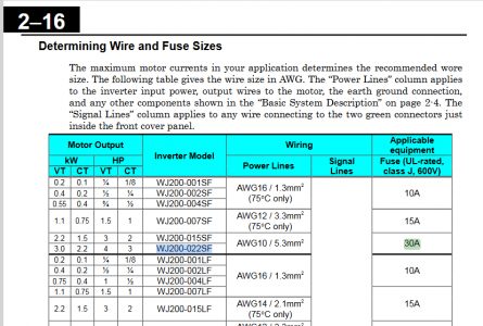
In the manual, it says for this 2.2kW device the input should be fused at 30A and the wire size should be 10AWG. See the attached table.
I suppose these specs. also try to take into account the fact that power line input voltage can vary, the inverter is not 100% efficient, and that the output voltage, frequency, internal switching frequency, and load can vary; and the inverter is designed to control acceleration both during start up and during braking. Of course there are other differences such as the work environment/temperature.

By the way, the 2.2kW is the steady state maximum output power to the motor, not the input power to the VFD, nor it is the instantaneous or peak power. I suppose if you are never going to load the motor down then the over all power needed can certainly be less. (A compressor is an ideal example of the issues. A compressor takes a lot more current to start up when the tank is already partly pressurized than when it is empty. This is because the load is much larger. It takes longer for the motor to start, drawing a lot more current during startup. Hence, it requires a much larger fuse to get started than to run once it is up to speed.)

1710102362400.png


The model 022L requires a higher temperature wire and then it can be connected via 12AWG.

Good Luck

Dave L.
 
Only trying to help....

Many sizes, models, and quality of VFDs out there, and yes a lot of opinions about what these things should do and how they should perform. These conversations are tainted by the concept of a generic VFD and many different installations. So, for the most part, I went by the manufacturer's specs and instructions.

There are two main issues associated with wire size. 1) Is the load so large that the wire gets hot and causes a fire. 2) Is the wire so small that it supplies a smaller voltage to the load than the load wants to see causing the load (VFD or motor) to fail (similar to a brown out). In the end you get to decide what you want to do as long as it meets electrical code (or that no one ever finds out). The fuse size, and code to some extent, simply tries to prevent item 1, the fire problem.

This is the model I mentioned that I used for my PM1440GT (3HP 3Phase) conversion:
The 420 page manual is here: https://www.hitachi-iesa.com/sites/default/files/supportdocs/WJ200_Instruction_NT325X.pdf

Hitachi WJ200-022S Model:
Input voltage: S=Single-phase 200V class, if there is an extra F at the end it stands for the keypad type
Applicable motor capacity in kW: 022 = 2.2kW

In the manual, it says for this 2.2kW device the input should be fused at 30A and the wire size should be 10AWG. See the attached table.
I suppose these specs. also try to take into account the fact that power line input voltage can vary, the inverter is not 100% efficient, and that the output voltage, frequency, internal switching frequency, and load can vary; and the inverter is designed to control acceleration both during start up and during braking. Of course there are other differences such as the work environment/temperature.

By the way, the 2.2kW is the steady state maximum output power to the motor, not the input power to the VFD, nor it is the instantaneous or peak power. I suppose if you are never going to load the motor down then the over all power needed can certainly be less. (A compressor is an ideal example of the issues. A compressor takes a lot more current to start up when the tank is already partly pressurized than when it is empty. This is because the load is much larger. It takes longer for the motor to start, drawing a lot more current during startup. Hence, it requires a much larger fuse to get started than to run once it is up to speed.)


View attachment 481900


The model 022L requires a higher temperature wire and then it can be connected via 12AWG.

Good Luck

Dave L.
12 ga wire is perfectly well protected with a 20 amp breaker. Is that in dispute? There is near zero line loss at 50 ft. I'm not buying the VFD you are using so I'm not sure what to say. I've read the manual on the vfd I'm looking at and it just says 220v and 16 amps
 
12 ga wire is perfectly well protected with a 20 amp breaker. Is that in dispute? There is near zero line loss at 50 ft. I'm not buying the VFD you are using so I'm not sure what to say. I've read the manual on the vfd I'm looking at and it just says 220v and 16 amps+
IMHO, I would go with what the manual for your VFD says. 12 ga wire is plenty enough, 10 ga would be unnecessary. 16 A @ 220v = 3,520 W / 746 (watts per hp) = 4.7 hp at that you are good with the 12 ga. And you only have a 3hp motor, so you'll be drawing even less current, probably around 10 amps. And as you say, a 50' run is negligible resistance.
 
I changed my mind on the wire size. Eventually I want a Precision Matthew's PM-1440HVT-2 14″x40″ H.D. Vari Speed Ultra Precision Lathe.


It has a 5 hp motor and the instructions call for a 30 amp circuit. It will go in the same place as the old one when I can afford it someday so I will kill two birds with one 10-2 wire.

The 12-2 will become a new circuit on a wall I need a couple outlets on.

I'm still leaning toward a 5 hp rated vfd for safety, which is still rated for under 20 amps.
 
The PM1440HVT should be a nice machine. I am happy with my PM1440GT. The HVT is very similar looking from the pictures, especially the threading and feed gear box , but obviously the machine has the VFD, or something like one, already built into the machine. So this part, the spindle speed gear box and drive are different. I also believe that the bed and maybe other structural parts are heavier.

You might think about the following wiring technique that I figure out, which was new to me, but not to others. Maybe it would be of value to you or others and can potentially save you some $$$. When I was rewiring my 1930 house, I ran 12-3+Gnd around my long basement shop wall as a single 220 circuit. At the breaker box a 220V 20Amp breaker is used. The line runs along the ceiling at the wall. Every so often I dropped it down to provide a wall outlet, so I had outlets every so many feet. However, the outlets boxes can contain a single dual 120V outlet plugs, but they have their separation tab broken, so that they are electrically isolated. The connections to the wires has one hot wire to the top plug and one hot wire to the bottom plug. The neutral is connected to the down (neutral) side of both. The ground wire obviously goes to the ground tab on the outlet as well as to the metal wall box. So that the top outlet is on one 110V side of the 220V service and the bottom outlet is on the other 110V side of the 220V service. So one can plug two 110V tools in, at the same location, each of which can pull 20 Amps, or you can plug in a single 20A 220V device, by simply changing the outlet plug type. You can even put a 220V plug in parallel with a pair of the 110V plugs. If you exceed the 20A breaker rating, on either side, it throws the breaker. There is no circumstance where the neutral is carrying more than its 20A rating. In fact, if the 220 outlet draws power the current flows through the two hot wires and not the neutral. Or if you have two devices connected to the two 110 outlets and they are of about the same load the neutral again carries no current. Totally within code and totally save, but is very convenient, especially when dragging the wire through walls or holes in joists or studs. Pulling two wires to get two 110 circuits is a lot more trouble. If you also need a 220 service that would imply running yet another wire.

Good luck with your lathe. I did not see where you mentioned the model or make of the old lathe. What is it?

If you have interest, I created a Workbook /spread sheet to compute all of the possible threading gear configurations. It is posted and a link is provided below. There are a lot more possible TPI values than are typically listed on a lathe or even the manual. Even if your model is not one of the ones I included in the workbook, the workbook is designed to allow one to easily add different lathes. It works very well and is especially handy for finding TPI values which are not always accessible via the standard configurations or for which you might be missing an external gear. I recently improved it, removing some bugs and minor errors, but have not posted that yet. I need to clean it up. Also, when you get your 1440HVT, I think you will find that the sheet for the 1440GT will already work. Anyway, here is the current version:

Nov. 6 2023 Excel workbook file name: TPI_ManyLathesRev1 NB06_0054.xlsm

Dave L.
 
I would check your electrical code and the VFD manual as to breaker size/fusing. NEC requires it to be at least 125% of the input rating amps of the VFD, has nothing to do with the motor current. The fuse breaker rating listed for the PM-1440HVT-2 is 30A at 3 phase, single phase it would be expected to be ~43A. In addition VFD can drive a motor at up to 200% of FLA for 1 minute, higher for shorter periods. Wiring/sockets are typically designed to handle 80% load of the breaker/wire size, not 100%. One reason you see a lot of house fires started from people using 50A sockets for their EV charging at over 40A. At the end of the day the breaker protects the wire, not the device. In order to use a 3 phase input VFD on single phase you typically upsize the VFD by a factor of 1.7-2 depending on the load/machine. The Eisen 1440EV which is the same manufacturer uses a Yaskawa V1000 VFD 7.5 Hp, I assume the PM/QMT Delta also uses a similar sized VFD. I would contact them as to the single phase breaker size and wiring required for their lathe.

The HY's and similar have about a 10% short term mortality for one reason or another, in most cases they are just replaced if you buy from HY (amazon). You can read the reviews. On more challenging applications like poston compressors the filure rate is up to 25%, unless significantly oversized. I found that their terminals did not support the current ratings of their models, in some cases the tracings and internal wirings went up in smoke. Since you are using this in a low stress situation, probably any VFD will work. I would have some concerns with very old motors as the insulation breaks down, regardless if it is a dual voltage motor. Typically a dV/dT filter is used, but in this case the motor would be a toss if it failed.
PM says it will run on a 30 amp circuit. They did not specify 3 phase. I'll call and ask.

I'm looking at using a single phase input vfd designed to handle a particular load. There are people here who disagree and agree. The article I posted before says the starting current can be held to 100% to 150% of the fla.

Eta: I sent PM a message asking if a 30 amp single phase 220v circuit will run the lathe. I'll post the response here.

ETA: PM confirmed that the
PM-1440HVT-2 14″x40″ H.D. Vari Speed Ultra Precision Lathe
Will run on a 30 amp 220v SINGLE PHASE circuit.
 
Last edited:
PM says it will run on a 30 amp circuit. They did not specify 3 phase. I'll call and ask.

I'm looking at using a single phase input vfd designed to handle a particular load. There are people here who disagree and agree. The article I posted before says the starting current can be held to 100% to 150% of the fla.

Eta: I sent PM a message asking if a 30 amp single phase 220v circuit will run the lathe. I'll post the response here.

Are you using bound cable like Romex? Or are you using single conductors like THHN?

My shop is wired with single conductor THHN in conduit. My 3hp South Bend 13" lathe on a VFD has never had ANY issue with 12gauge/20amp shared circuit in my hobby shop. My 5hp single phase air compressor has never had a problem on 12gauge/20amp breaker either. I know my air compressor is a much larger load than my lathe and being a single phase motor draws a MUCH larger starting inrush current. The 20amp breaker is there to keep the wire from overloading, heating up and causing a fire. I have NEVER had a breaker trip.

There is nothing wrong with using 10 gauge if that is the direction you want to go.
 
Last edited:
Precision Matthew's confirmed that the PM-1440HVT-2 will run on a 30 amp 220v SINGLE PHASE circuit.
 
Back
Top