Tips for Your Electrical Panels!

Well, it seems I am a bit behind the times. My copy of the NEC is 1994, by the way. But there are many cases where the NEC (and NFPA) have no say in the way things are done. I have made it my practice to make my installations safe, not necessarily code compliant. Yes, there are places where this can make a difference. And remember, codes are minimum standards for workmanship anyway.

I will concede that I am in (serious) error here. But I will continue to do things the way I have for near 50 years now. Such as tinning a stranded wire where it fits under a screw head. I do use crimped on lugs on a regular basis. I have hundreds on hand. But when I think it will work better and be safer in the long haul, I will continue to use my own methods. And signing this can be taken as my signature on the subject.

Bill Hudson
.​

I worked for a company back in the 90's building CNC machines and they had switched to wire ferrules in, at the time, recent history. Prior to that, the common practice was to tin wires using solder pots when terminating smaller gauge wire in terminal blocks. The only down side in my experience to using wire ferrules is, that it can sometimes be difficult to terminate two wires in a terminal. I don't know what the accepted practice is for 2019, but back then you were allowed to terminate up to two wire per side of a terminal block. I too have not heard of properly tinning a wire prior to termination being problematic. Since I do not own crimpers and ferrules I would not hesitate to tin a wire prior to termination.
 
I should clarify that I only use rivet nuts at home as I have sometimes used thinner aluminum sheet metal to save cost when I buy an enclosure on ebay and it doesn't come with a subpanel. At work we always drill and tap the subpanel or sometimes weld studs to it for heavier devices. I found the rivet nuts to be really helpful in my current build, however the right way to do it is buy the heavier gauge steel subpanels from your enclosure supplier.

AutomationDirect is a great source for inexpensive components, I've use them for over 10 years. As to subpanels, I've always drilled and tapped holes. I have a project at work coming up and plan on using a perforated subpanel. Slightly thinner at 14 gauge but they have 0.125" holes on 0.250" spacing. I think this will make mounting components much easier.


Great idea using rivet nuts for home projects! Thanks for your well thought out and informative post. It will be a great resource for first time builders.
 
Nice review. Pretty much follow most of what you have outlined, I prefer to use spades with terminal blocks in some applications. Typically I just tap the back plate for mounting, reduces cost and something like a VFD/braking resistor will sit flush against a metal surface which aids in heat dissipation. Would use threaded studs for heavier mounts like transformers/chokes, etc. Shielding and grounding can be a big problem, and often is not as straight forward as one thinks. Keep your signaling wire away from AC and higher voltage wiring. Read the manuals and follow what they recommend as a starting point. Test your systems thoroughly, I always build in safety redundancy in my designs when possible.

Soldering of wire is not recommended for terminal connections and crimps, it will cold flow and loosen. In addition it is associated with breakage due too fatigue in wiring that experiences vibration/repeated movement. I recommend using higher end crimps (like T&B) that are nylon insulated and have a double wall crimp typically of copper alloy which fuse with the wire. I have tried pullout tests and the wire breaks before it can be pulled out. There are a few exceptions to soldering seen in the marine environment where salt will get into crimps and eventually corrode the wires. What I read a while back was you always crimp the wire first and then flow the solder at the tip of the crimp, being careful not to flow too much solder so it does not wick down the wire. This is outline in certain cost guard guidance's. An alternative is using crimps (like 3M) that have fusible shrink tube insulator, this seals the wire completely after crimping. I cannot emphasize enough the importance of a good crimper with the proper die for the type of crimp used. I use to have all kinds of poor contacts until I upgraded to better crimps and a decent crimper that ran around $70.

One of my pet peeves is people using crimpers for non insulated terminals on insulated terminals. Also, I think it should be illegal to sell vinyl terminals. Anti-wicking tweezers work great to prevent solder from wicking when soldering crimped, non-insulated terminals.
As far as tinning a wire, if the strands are thinly coated such that the strands look like they're tin plated, the terminal block connection would stand the test of time. I never had a problem with creep like one would have with aluminum wire as in old house trailers burning down due to aluminum wire creep. If you have a solder glob after tinning, I can see that creep can occur. I replied to another post stating that in a home brew scenario, I would not hesitate to properly tin a wire prior to terminating it in a terminal block. But, while composing this reply I decided to check the "interweb" and found this from the T&B site, 'The problems with tinning wires' which I think all of us "wire tinners" should read.
Their example shows a wire with excessive solder. Maybe they need more wire ferrule sales?
So, I thank you for statements regarding the cold flow and terminal loosening problem. I guess I'm not too old to change my evil ways :)
 
The only down side in my experience to using wire ferrules is, that it can sometimes be difficult to terminate two wires in a terminal. I don't know what the accepted practice is for 2019, but back then you were allowed to terminate up to two wire per side of a terminal block.

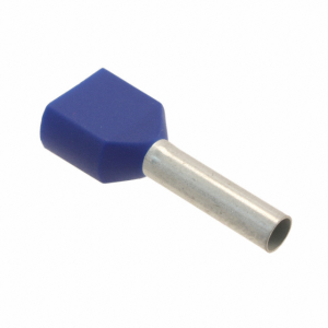
They make ferrules for that :) You can usually get ferrules for each wire size in single and double ferrules. They are also available in multiple lengths so you don't need to trim the ferule after crimping.
1574345334496.png

I too have not heard of properly tinning a wire prior to termination being problematic.

I am not an expert on the matter, but I believe the industry shift away from tinning wires began with the aerospace industry's issues with tin whiskers and creep. Since the alloys used in soldering melt at relatively low temperatures, they can experience creep (cold flow) at room temperatures leading to a decrease in terminal tightness in screw down terminals. Whiskers can also spontaneously grow from solder and form long structures which can short out connections. When the EU passed RoHS restrictions in 2006, most of the world's electronics industry shifted away from leaded solders in order to be allowed to sell their products in the EU. Lead-Free solders are much more likely to form whiskers.


I think that a tinned wire connection is perfectly fine for nearly all connections, but I never see them done at work or at customer sites. The only exception is when a product comes with tinned flying leads from the manufacturer.
 
I tend to tin stranded wire, but just do it at the very end of the wire to hold the ends of the strands together. This way you are mostly pure copper under a screw type connection, so should not creep, which can be an issue if you tin the whole thing.

Crimp type screw terminals are probably better, but I still tend to hit them with some solder after crimping, but not so much that it flows under the insulation, which can stiffen things up and cause problems.

I also have one of those square crimpers and the ferrules and they work great for low voltage control connections. I still tend to hit the ends of them with a little solder, just in case.

I am not into the more complex control panels but for simple VFD setups I will go with NEMA rated sealed enclosures and make my own panel from some 1/4" aluminum and drill/tap as needed.

Kudos to the thread authors and contributors as lots of good info here!
 
Motorsports and off shore power boat racers do not tin the wires. The transition from the solid tinned end and the individual strands is a stress concentration point. Fatigue failures can lead to DNF. No Bueno.

X2.
 
Back
Top