This seems too simple - differential screw adjustment, am I missing something?

Joe Pie to the rescue again. Look at his threading video where he shows how to just use one wire. Simple, logical and much easier.
Is there also a reference for this? My 17th edition Machinery's Handbook only shows a single wire method for acme threads and notes it isn't very accurate. Quite a write up on the three wire method in there. The handbook also mentions having a micrometer fixture attached to the lathe that guarantees being square with the threads. It says if the micrometer is perpendicular to the screw then one only needs two wires. I can easily do two, it's the third wire that has a mind of its own. I will check out the video.
 
Finally back to here. Just testing if I understand this 1-wire stuff. Trying to put it all together, so I can make a chart for myself that even a simpleton can follow.

From what I understand, PD = 2T - D - k, where PD is the pitch diameter, T is the measurement over the screw and a single wire, D is the major diameter, and k is a constant which depends on the wire size. We pick k to be "optimal" for the pitch measurement. Therefore we can solve for T, and bound the 1-wire measurement.

This would result in T = (D + PD + k)/2? If I know spec limits for PD, and D, then one can bound the 1-wire measurement between two limits?
As an example: (forum mangled the table a little, but I think it is apparent what I mean)
Size​
One wire Meas T [mm]
max
min
nom
Wire Size [inch]
M6 x 1.00​
6.1304​
5.9844​
6.0574​
0.024​
M6 x 0.75​
6.09555​
5.97555​
6.03555​
0.018​

Burs (and precision) aside, is this what one would want to go by? This stuff makes my head hurt... Here's what I am working with.
 

Attachments

  • onewirethreadmetric.ods
    18.2 KB · Views: 3
Last edited:
My wire set says the wires for measuring 1mm pitch should be 0.024", but they measure 0.0235". (0.5969mm) (Two different micrometers, they both measure the same. A Shars old fashioned mic, and a brand spanking new QuantuMike.) So the constant isn't correct for these wires. The wires within the set seem to match, but don't matter for a 1-wire measurement.

The constant k is defined by k =-(0.86603 x pitch - 3W), (Machinery's Handbook) so in metric, that would be k = -(0.86603 - 3*0.5969) = 0.9247, rather than 0.9628 for pitch = 1mm, and wire size 0.024". Hmm, good thing I created a spreadsheet, this could drive one mad... It's only 0.02 mm but, I'd rather things fit then not.

New table for my actual wires:
Size​
One wire Meas T [mm]
max
min
nom
Wire Size [inch]
M6 x 1.00​
6.111​
5.965​
6.038​
0.0235​
M6 x 0.75​
5.968​
5.848​
5.908​
0.0175​
 
It's not the "sloppy fit" I'm worried about, it's more of completely missing the mark. Not positive the math is right, just yet. It's kind of easy to fool oneself that you did it right....

I want to extend my spreadsheet for all the actual wires in my set (using actual measurements of the wires) and most if not all of the pitches I'd cut. Then I'd have a worksheet in my shop to refer to, rather than trying to figure it out every single time.
 
Good idea. I take it you have bought into the one wire method.
I don't know if it has been widely used before being shown on Joe Pie's site.
Given how simple the explanation is, why would people still fight the 3 wire method?

For me the same applies to single point threading away from the chuck.
I started with the standard 29+- degree method moving both the compound and cross feed each new cut.
Had to run really slow and risk a screwup moving both dials.
I can now run faster, use the DRO with a set point and feel much more confident.
For those opposed that's fine, nothing better than a Chinese fire drill.
Not sure I've bought into 1-wire just yet, but it sure is less fiddly than dealing with 3 wires! I'll use it for this project and see how it works. If it works out ok, I'll continue to use it.

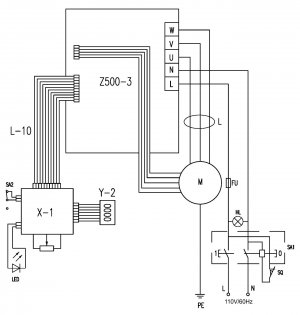
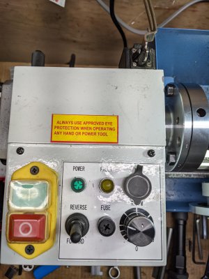
I'm not opposed to SPT away from the chuck at all. I think it is pretty neat. Just haven't set it up yet. If I get in a situation that needs it (or scares me!) I will try it. Normal threading isn't that bad, save for the stop. If I can figure out the wiring diagram of my mini-lathe, I may install a repositionable E-stop switch as well. The diagram is a little confusing, and might only be "representative" of what is actually there, same as the parts diagram... Physically, the switch looks like:
mini-lathe_wiring_diagram.jpgPXL_20210430_131914171.jpg
I think if I put a NC switch in series with "SQ" this idea should work. It's not an e-brake, but for small parts (and chucks) with low moment of inertia, it should work. Not sure where "SQ" physically is, but I hope it will be apparent when I open it up.
 
Getting frustrated by some of the old cheap tooling that I have. I took a "low quality, otherwise known as HF" M6x1 die and it loosely spins on both a known good M6x1 screw and my SPT M6x1 rod. A known good M6x1 nut spins on the known good M6x1 screw, (more snuggly than the die) but not on the SPT M6x1 rod. The nut jams after 4-5 threads. So the die is "loose" and probably is not in spec. I have a corresponding cheezy M6x1 tap, from the same tap and die set, and it's too large to go through the known good M6x1 nuts. Clearly this is a tolerance issue. The HF tap is consistent with the HF die, meaning it too is sloppy and out of spec. Since the tap (and die) are tri-lobed, there's no direct way for me (that I know of) to measure them for major or minor diameter. Is there a way to measure tri-lobed stuff?

The major diameter of the SPT rod is slightly smaller than the quality screw, so I think this is telling me that the pitch diameter is still too large. The die is too large, it cuts no threads on the SPT rod, so I have to match the thread and continue to SPT it deeper. Been more of an education than I bargained for. Quite the introduction to tolerances... Back to the lathe.
 
Back
Top