This seems too simple - differential screw adjustment, am I missing something?

I haven't tried that in recent memory. Looking at the relative position of the screws, I could see it might possibly rotate the assembly in the horizontal plane up until it uses up the slop in the keyway. I can try it, (and will) but it seems one could have it correct in only one position of the quill. I'd like to be able to horizontally translate the tailstock, perpendicular to the the lathe spindle as well as having a minor rotation.

As I understand it, the set screw allows horizontal relative movement if it is loose, AND the bottom screw is loose. The set screw does not really change the relative position, it is only a lock. It could have the ability to affect a very small amount of rotation. The idea for a screw like in tailstock adjuster is to be able to easily set the horizontal position. A differential adjuster mod (in my opinion) would make a finer adjustment possible. Whether or not it is really practical, that depends on my limited machining abilities, at the moment.

If my understanding is not right - please correct me! I'm on HM to learn.

Practically, I can tap the tailstock into alignment with much iteration and muttering. I was hoping a differential screw would minimize the blue words and increase the precision. It certainly has been interesting reading about it and designing it.
 
pics would be useful, but when I went looking for minilathe tailstock pics it turns out this is a common problem, with a mod detailed on littlemachineshop.com itself
Tailstock adjuster
so looks like I was the one that was wrong! Sorry about that, I just couldn't imagine that this adjustment wouldn't be a normal feature on a lathe.
 
@mattthemuppet2 no worries. Hadn't thought of checking LMS. Good idea! Think I'll modify their design. I like the turned hex piece. Still going to do the differential screw. If I captivate the hex nut on the top or side (with an added piece), rather than the bottom which touches the ways, I can rotate the nut to quickly do the coarse adjust. Then lock the nut and do the final fine adjust. Back to to drawing board with some additional ideas!

I did coarsely re-adjust the tailstock, it's much better now, but I will make an adjuster with a differential screw. Think the idea is really cool.

Mini-lathes are a kit. As you found out, they just leave some features out to hit the price point. So we get to mod them to make them useful enough. Guess it's what one unwittingly signs up for when buying one.
 
If you run into an adjustment range issue you might be able to fix it by offsetting your bar with washers on either side. If you also have a mill, you could mill a slot in the middle of the bar instead -- it would look a little more refined, but the washer scheme would work equally well.

The tailstock alignment problem is a common one for these lathes, so you will find a number of solutions out there if you look around. But I haven't seen anyone else using a differential screw. Please let us know how it works out!
 
Definitely need to do this mod. Was a little concerned about stick out, so wanted to drill the end of the screw for a dead center. The center drill won't center. What a pain - especially for small diameter parts - like the differential screw I am making! Thinking ahead, there is offset in the vertical as well, but I want to fix the horizontal first, as it should be a lot easier.

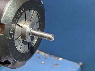
Have 14mm of the 5mm screw turned down to 3.9mm. That would be 20T at 0.7mm pitch. Unfortunately, I can't get the threading bit in close enough to cut all 20T. I need to modify the threading tool or the fixture. I could deepen the fixture counterbore some more, so a few more 5mm threads stick out. I also need to cut a section at the minor diameter to give me some breathing room to stop. This little screw is giving me quite the education... I probably need a 35 - 40mm screw not the 30 that I have to make exactly what I need. This one is good practice, however.
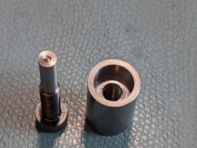
PXL_20210423_173541868.jpgPXL_20210423_174734475.jpgPXL_20210423_175529006.jpg
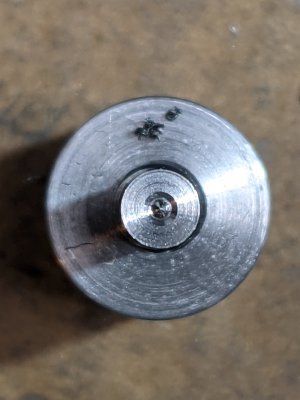
Slowly getting there... You can see the center drill made a point, at the end of the screw not the hole I'm expecting.
 
Slowly getting there... You can see the center drill made a point, at the end of the screw not the hole I'm expecting.
Yow, that's irritating.
Can you stuff in some shims? At least get within a millimeter?
 
The screw on the bottom of the TS is accessible when it's on the lathe bed if the clamp is removed. You may be able to improve the alignment if you loosen the screw , then install a piece of drill rod in the TS drill chuck. Grasp the other end of the rod with the headstock chuck to pull the TS into alignment and tighten the bottom screw. You also will need to loosen/tighten the set screw that pushes against the base's vertical boss.

Now, it actually may not be too easy to get an allen wrench in there to tighten up the bottom screw. If that's the case you are not SOL just yet. Go ahead and loosen the screw before you install the TS, use the drill rod as described above -- but then measure the offset of the top relative to the base. Remove the TS and use your measurement to reproduce the offset, then tighten the screw.

Caveat: I haven't tried this myself so there could be some "gotchas" I haven't foreseen. On the other hand, it doesn't require any mods you can't undo. It also assumes that the TS height is about right, and the angular alignment (relative to the bed) is about right. That could be a tall order, considering the average build quality of these things -- but shims can take care of most of those problems.

I had a number of issues with my TS but corrected them by milling it to correct the problems. You may not be in a position to take that approach.
 
It was within 0.5mm when I started. This is a grade 12.9 bolt - probably should have used something a little less tough.

First attempt failed, but I think I know why. So I can try again.
  • Too much initial stick out when attempting the center drill - Will make another fixture (threaded sleeve) to minimize stick out for initial drilling. I would really like to get a center in there for threading such a small diameter
  • Set up the gears wrong initially (switched B & C position!) Fixed that.
  • HSS threading tool had too big of a flat on it to support the 0.7mm pitch! Oops! Found an insert with 0.002" nose on it to fix that problem.
  • The concentricity is hard to control due to the fit class of the threads
  • It was the first time ever threading metric on my imperial threaded lead screw. It didn't take long to figure out, but it was added to the mix
  • The 1mm wide parting blade height wasn't right - took me a while to realize this. The height becomes more critical when machining small diameter stock. (I had set the height too high and the blade was rubbing, not cutting.) Switched to a 1.5mm parting blade and adjusted the height closer.
So it was a comedy of errors. Not my best day. I will try again with the M5/M4 combination. If it fails, it is possible to go up in size to M6 x 0.75 (fine thread) and M5 x 0.8. (Or M6x1 and M5x0.9?) Threading the M5 might be easier. One advantage of this combination might be that the Larger diameter won't bottom since it is finer pitch than the inner diameter. The disadvantage is the adjustment range will be even smaller.

For my initial attempt the compound was at 90 degrees, not 29.5. Don't know that it matters for such tiny threads. Does it?

"This seems too simple", apparently it isn't!
 
I always thread @ 90 degrees, easier. So is threading away from the chuck. Thanks Joe Pie.
 
I do have a mill. It's unclear to me where the reference surfaces are, and how to deal with the 90 degree prism cut. I don't trust my abilities to do that without tossing the piece. There's other places to try surface removal, but I'm just too new at this game to try it. If I had local guidance, maybe I'd try it.

Thinking about the screw some more, I don't think there is a reason to shrink the diameter of the screw for the end. If there is a tap available at say 6mm x 0.75, one could start out with 1/4" rod, turn it to 6mm, thread one part at 0.75mm pitch, and the other part at 1mm pitch. This gets rid of one problem, being the floppiness of the 4mm section. I think I can fit in a 6mm piece. Then I'd knurl the end and press on a knurled wheel adjuster. That's 250um per revolution or about 0.0098"/turn. That should be ok. That's about 0.001" per 1/8 turn.
 
Back
Top