Hi folks - I'm a new guy so a brief introduction first. My full name is Rick Bruner and I reside in upstate NY (Syracuse area). I have been a woodworker for quite awhile (note that longevity doesn't necessarily equate to skill and over the last few years have been drawn in to the restoration/rebuilding of old WW equipment. 45 years ago i took a shop class that was required in my associate degree program - that involved running a lathe. That was the last time I did nay metal working to speak of - but I have always felt an attraction to the field. In anticipation of my recent retirement I bought and sold a number of small metal lathes (a no name, several atlas lathes, etc) - the more reading I did the more I realized I wanted a South Bend. One came up for sale last spring for a reasonable price and I jumped on it. I sold all of the other lathes I had been accumulating to focus on the SB. I recently started the rebuild process and thought I would document it here as well as several other forums - my strategy is to get as much exposure as possible because I know I will have a ton of questions.
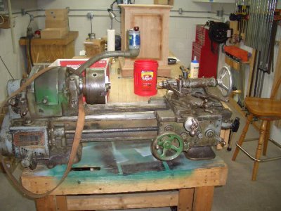
The lathe is a 1939 9" X 36" south bend referred to as a "Heavy 9". The heavy 9 is almost a ten inch 1-3/8. It is capable of accepting 5C collets. This spindle is bigger than some 13" lathes. The previous owner indicated that the only difference between this lathe and the heavy 10 was 1/2" of swing. It is billed as a bench top on the serial card with an undermount drive - again a very unusual drive for a 9" lathe according to south bend. The bench it was previously on was basically a set of cast iron legs with a wooden plank top and a sacrificial hardboard cover. The more I looked at pictures and learned a little bit the more I didn't like the bench idea so I started looking around and was able to find a cast iron pedestal base with the underdrive mount, the cast iron TS leg and a chip pan. The seller is fairly well known and we were able to make a deal at a reasonable price. The problem was that it was 4 hours away. I was able to make a deal with another guy where he picked up my lathe stuff and I picked up a mortiser for him and we split the travel distance for an exchange.
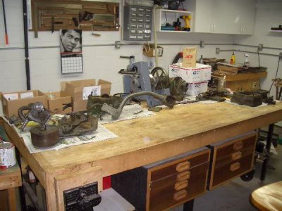
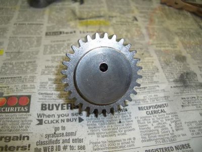
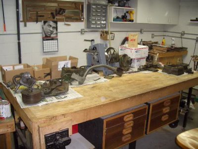
The current state of the rebuild is that the drive and base parts have all been disassembled, cast iron parts were all shot blasted, machined parts/fasteners were all wire brushed and everything has been painted (some still drying). I tried to replicate the SB color based on one of the gear guards. I went to sherman williams and we matched it by eye. It seems close to me and I'm not really hung up on exact replication. My plan is to use the greenish/gray SB color with some black accents. I am brushing everything as I don't have spray equipment and its getting too cold in NY to use rattle can outdoors. I'll post some pictures after I start the re-assembly. There some links below to other forum threads (hope that is OK?) that document some of my initial efforts. I've changed horses a couple of times - started with the tail stock and put that on the back burner, completed the original drive and then decided to use the one that came with the pedestal base - so it may get a little confusing.
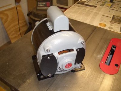
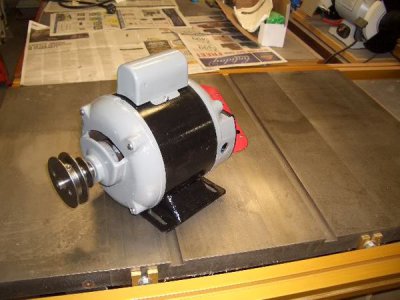
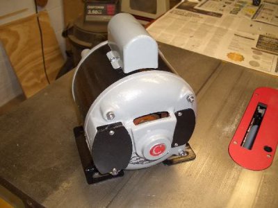
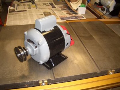
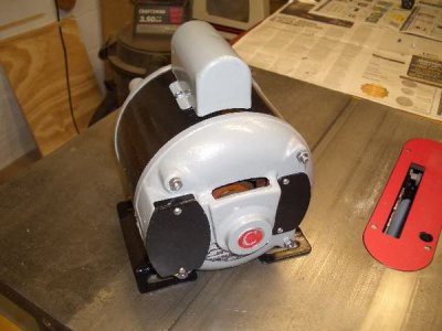
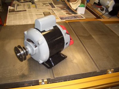
When I got the pedestal base and new drive - it had what was reported to be an original motor - it is a 1/2 HP, single phase, dual voltage, 1725 capacitor start motor with external reversing. It took me awhile to figure out that the motor leads had been previously connected inside the motor for 110. Once I discovered that I was able to re-assemble the motor and get it running. The motor has been disassembled, cleaned and painted and is also in the "paint drying stage".
The next phase is to let the paint dry a few weeks and then reassemble all of the base and drive parts. I'm expecting a buffer in a few weeks which I need for a few of these parts. In the meantime I may start some of the main lathe disassembly. There probably won't be a lot of progress until after the holidays.
here's a link to a thread about the motor
http://owwm.org/viewtopic.php?f=82&t=107029
And here's a couple of more links - the first is to an OWWM thread. In the future I plan on posting to each of these forums so I won't be linking as much. Note that the posts on these other forums are nearly identical so either one should catch you up.
http://owwm.org/viewtopic.php?f=77&t=103355
And finally here's a picture of the lathe as I received it. Thanks for looking and thanlks in advance for all of the help I am going to need.


Last edited by a moderator:


