-
Welcome back Guest! Did you know you can mentor other members here at H-M? If not, please check out our Relaunch of Hobby Machinist Mentoring Program!
You are using an out of date browser. It may not display this or other websites correctly.
You should upgrade or use an alternative browser.
You should upgrade or use an alternative browser.
Superfly Cutter
- Thread starter ddickey
- Start date
- Joined
- Aug 26, 2013
- Messages
- 1,061
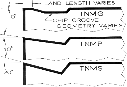
Blunt edge? Why would an insert have a blunt edge?
A land makes the inserts last longer. If you are hogging off material, a razor sharp edge isn't needed and is a liability as it's delicate and will break easily.
This image shows what i mean even though they are referencing turning inserts.

For a machine like yours, you want high positive finishing style inserts, as they will require less rigidity and power.
Yea, I needed to look at that insert again. It looked at first like the super-sharp aluminum insert, but a closer look shows the radius. You clearly know what insert you're using - sorry for the assumption.I may try again in a different material today.
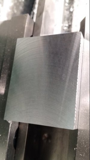
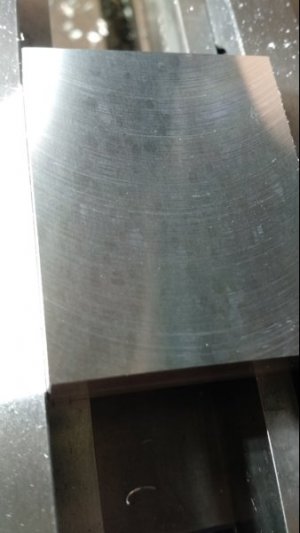
The insert is coated. It is Kenametal with a KCPK30 coating. Supposed to be used dry so I don't think that was the problem. It also has a T-Land edge. I tried another that had a honed T-Land edge with no difference. The radius is .039". I did try 900 rpm, appeared to be no difference. I agree I think it is a rigidity issue.
- KCPK30
- A multilayered TiN-TiCN-Al2O3-CVD-coated carbide grade with advanced Beyond™ post-coat treatment and a very tough substrate. KCPK30 has a wide application area in general and rough milling of steels and cast irons. It performs best dry but can also be used we
If you have, or can get, an insert with a smaller tip radius you may be able to get a better finish with the shallow cuts your mill can handle. Positive rake, sharp edge, small tip radius, light cuts - everything for an under-powered, floppy mill.
SO... we're back to rigidity. About the only other thing I can suggest - given my staggeringly inadequate machining experience - is to suggest bracing the column. There's an older youtube video of a guy who bolted big A-frame struts at the top and bottom of his mill column to a concrete wall and he indicated it stiffened things up significantly. When I was considering a G0704 or PM940, I half-way designed a mill table that incorporated a triangulated brace from the column top to the table bottom with the apex tied to the mill base. It would have stuck out another foot from the back of the mill, but would have reduced the mill base to column joint acting like a hinge. Would have done nothing for the table or base twisting, but probably would have helped a bit. I bought a different mill, so the design didn't make it off the napkin...
- Joined
- Dec 20, 2012
- Messages
- 9,422
Duane, is the cutting edge of your insert flush with the work? These inserts have a rather broad cutting edge that needs to sit square to the work. If is doesn't then you will have finish issues. I suspect the angle of your tool is off.
- Joined
- Aug 26, 2013
- Messages
- 1,061
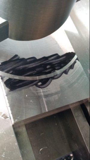
@ddickey If the angle isn't 45 degrees as referenced in this image adjust the cutter in the fly cutter body so that the angle is less than 45 degrees. Two or threes degrees less is fine, a few degrees greater could cause the chattering you have shown in previous photos.

You don't need to worry about getting it perfect. Unless your running a cnc mill it will be next to impossible for you to really take advantage of the wipper. At 2" and 2000 rpm (what you need to get a good sfpm), you would need to be cranking the handle at 80+ rpm just to reach the minimum chipload for the insert.

You don't need to worry about getting it perfect. Unless your running a cnc mill it will be next to impossible for you to really take advantage of the wipper. At 2" and 2000 rpm (what you need to get a good sfpm), you would need to be cranking the handle at 80+ rpm just to reach the minimum chipload for the insert.


