Stuart Beam Engine

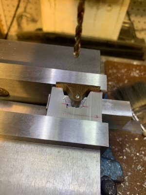
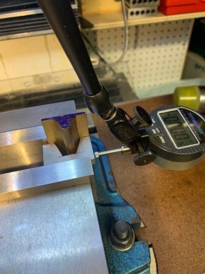
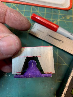
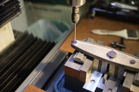
Now to the column base. Set the column capital in the vise registering the same orientation of the machined face to the vice fixed jaw. Indicate on both jaws.
001.jpg

Divide by two on the DRO and set the Y to zero.
003 - Copy.jpg
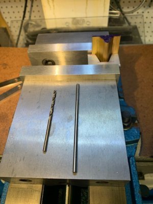
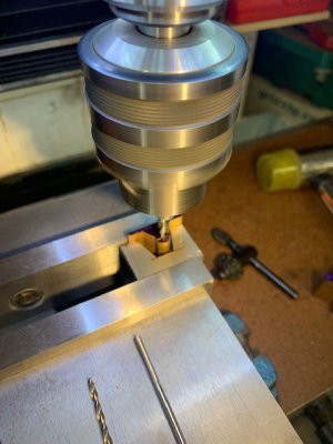
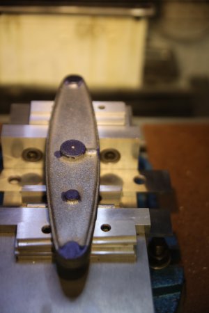
How about that, the center drill lines up perfectly with the lathe center hole!
002 - Copy.jpg
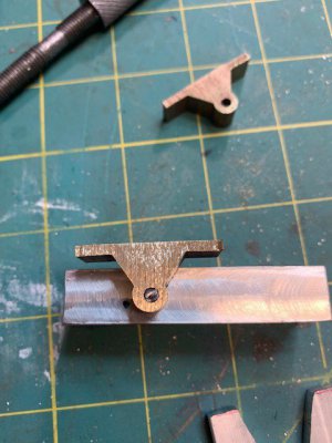
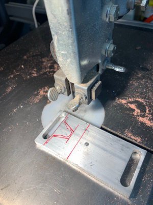
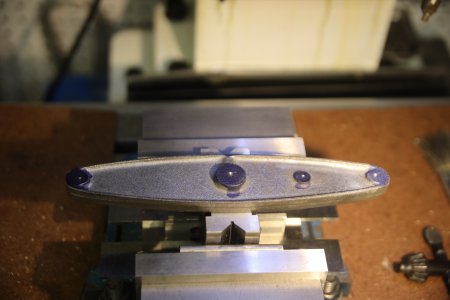
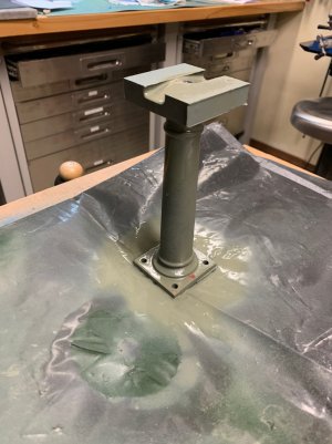
Drill the base plate holes and test fit. Wow, trig really works.
004 - Copy.jpg
005 - Copy.jpg
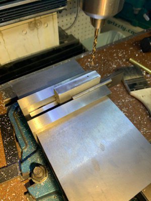
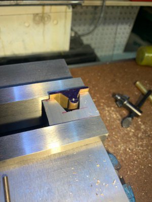
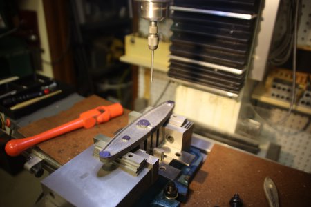
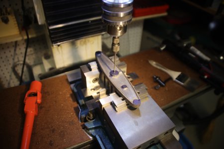
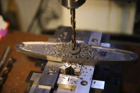
While I'm on a roll, time to machine the entablature beam mounting surfaces and holes. Set the top machined face against the fixed jaw with a dowel against the cast side. Indicate against the machined surface and against a gauge pin in the previously drilled beam block mounting holes to set my x and y coordinates on the DRO against known features.
009.jpg
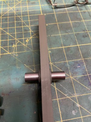
Mill the 3/8" groove .029 deep on both sides to hit the 2" width. Locate, drill and tap the entablature mounting holes, paint unmachined surfaces with etch primer(Thanks Kieth Appleton), oil the machined surfaces and we are on to the entablature beams.
011.jpg
 

Attachments

  • 010.jpg
    010.jpg
    521.9 KB · Views: 13
Last edited:
Isn't that great!!
I have just recently discovered the magic of my DRO.
Love it. Looks great.
Keep em coming.
 
Isn't that great!!
I have just recently discovered the magic of my DRO.
Love it. Looks great.
Keep em coming.
Just looked up your thread on the PM research engine. I have been reading it since the beginning and didn't realize it. Very good work.
 
Entablature beams are next. Should be pretty straight forward. Start by setting up my fancy end stop to register the x axis of the beam. Register y on the fixed face of my vice.
16.jpg
Mark the hole centerlines to check the DRO(sometimes I forget to add .1 to my measurement for my center finder.)
19.jpg
Mill the surface for the watts parallel bearing support and the beam ends.
18.jpg
Set DRO for hole centerlines, locate, drill and tap.
15.jpg
Look at that, the holes line up with the column. If I didn't know better, I'd say I knew what I was doing.
13.jpg
Time to think about how I'm going to machine the watts parallel motion bearings that mount to the entablature beams.
12.jpg
 
I'm looking forward to it.
Please post pics as you go.
 
Bearing block time. There are 4 brass bearings, two for the watts parallel motion assembly and two for the valve connecting rod. Begin by flattening the base and checking it on the surface plate.
28.jpg30.jpg31.jpg
the extrusion is too long for my drill and reamer so I have to cut it in half.
39.jpg
Mark the hole centerline and indicate the edge to make sure I get close to parallel
49.jpg22.jpg
Need to be able to hold it this odd part with out crushing it, make an aluminum clamp block. Not pretty, but effective.
25.jpg24.jpg23.jpg
Drill and ream. Not perfect, but will work. Nice fit with a .125 pin gauge.
43.jpg42.jpg41.jpg
Now for a fixture to make sure when I mill to the proper thickness, the face is normal to the axis of the .125 hole.
37.jpg35.jpg33.jpg
Was a good idea in theory, but not rigid enough in practice. Had 20-25 thousandths in thickness difference from end to end. So how do I make sure I keep the axis lined up regardless. Time for another jig. Small machinist vice (Thanks Mr. Pete) with a .125 pin. Indicate off the pin to get the centerline and drill the clearance holes off this reference.
50.jpg
Spend a little time on the polishing wheel(after on top, before on the bottom)
32.jpg
They all fit, but I didn't drill and tap the base and entablature deep enough. I'll clean that up.
51.jpg
Now on to the beam. Lots of sand still in the casting.
52.jpg
 

Attachments

  • 21.jpg
    21.jpg
    101 KB · Views: 3
  • 38.jpg
    38.jpg
    76.7 KB · Views: 2
  • 36.jpg
    36.jpg
    61.2 KB · Views: 2
  • 34.jpg
    34.jpg
    63.6 KB · Views: 2
  • 46.jpg
    46.jpg
    72.3 KB · Views: 2
  • 45.jpg
    45.jpg
    58.3 KB · Views: 2
  • 40.jpg
    40.jpg
    61 KB · Views: 2
  • 48.jpg
    48.jpg
    77.3 KB · Views: 2
  • 47.jpg
    47.jpg
    55.8 KB · Views: 3
Last edited:
Well done.
Making the holding jig is a great idea.
I saw Joe Pi use a pin gauge the size of the diameter of the extrusion to center the spindle instead of marking it out. You get there in the end but making it easy and accurate is always a quest.
It seems like figuring out how to do it then setting it up takes 95% of the time.
Looking good man! good pics too
Please keep posting.
 
First thing with the beam is to remove the sand with a wire wheel and sand/file the gates/flashing off the casting. Use some Dykem and layout the center holes as a check for the DRO. Now how to fixture the beam in the mill. V blocks and parallels seam to do the trick.
3Y9A0761.JPG
Next, make sure I have enough travel. Dang, need to rotate the casting to be parallel with x axis of the mill.
3Y9A0768.JPG
Picture of the end supports didn't make it, but be confident that I didn't try to drill and ream holes in the end of a spring board.
Zero the DRO and make sure the alignment is proper with the holes at either end of the beam
3Y9A0766.JPG3Y9A0769.JPG
Drill and ream one 1/2" hole and three 1/8" holes.
3Y9A0774.JPG3Y9A0775.JPG
Nice fit with gauge pins.
3Y9A0776.JPG
Now make the beam pivot.
IMG_3878.jpgIMG_3879.jpg
Nice fit.
IMG_3881.jpg

Based on my last post I was going to be working on bearings/plummer blocks. Well my first attempt was a spectacular failure. So I am waiting on some new castings to replace the one I fouled up.
IMG_3870.jpg
Glue joint failed as I was doing the final machining. Notice the gouge in the casting and the uneven material around the bore. Should have listened to Joe Py and not use the superglue option. Still trying to figure out how I'm going to get these parts done.
 

Attachments

  • 3Y9A0762.JPG
    3Y9A0762.JPG
    1.9 MB · Views: 6
  • 3Y9A0764.JPG
    3Y9A0764.JPG
    6 MB · Views: 6
  • 3Y9A0765.JPG
    3Y9A0765.JPG
    6.2 MB · Views: 6
  • 3Y9A0767.JPG
    3Y9A0767.JPG
    6.9 MB · Views: 6
  • 3Y9A0772.JPG
    3Y9A0772.JPG
    7.6 MB · Views: 7
  • 3Y9A0773.JPG
    3Y9A0773.JPG
    7.1 MB · Views: 6
  • IMG_3880.jpg
    IMG_3880.jpg
    61.5 KB · Views: 8
Made three quick parts for the Watts linkage. Finally figured out how to do the bearing/plummer blocks. That will be up next.Inked53_LI.jpg
 
Back
Top