Solenoid questions

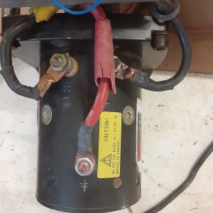
Ok, it is basically reversed left to right from the diagram I found. Then the one solenoid is flipped upside down.

I would start by adding power to the fat red cable, and ground. Then test the cable, and I assume it has a wireless controller. in or out should only activate one solenoid at a time.

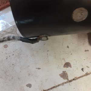
Give me a few hours and I will study your pic, and point out wher the motor wires go.
 
They are connected to each other with a piece of copper at #4 ,on each solenoid
 
Sorry I'm a little slow. I had knee surgery yesterday and supposed to be laid up two days in bed with elevation and ice
 
No problem, I have to run out for a bit. But see if the wires coming from the wire controller match this. Do not disconnect the PC board. With this, you should be able to hear each solenoid click for each direction. And hopefully the wireless controller also works. I think I have the wiring figured out, just need to take a second look with a fresh mind. I'll be back in a few hours.

e6765b1e23e7e6801133f6a8242e9eafbbcontrol.jpg
 
Here's the motor three wires on top one on bottom. I figure the center red one on top to be positive. The black one on bottom to be negative
 

Attachments

  • 20201208_133551.jpg
    20201208_133551.jpg
    633.7 KB · Views: 24
  • 20201208_133615.jpg
    20201208_133615.jpg
    631.1 KB · Views: 24
Did you stamp the in and out on the terminals? At the back end of the motor, you have the insulated terminal, and the back has the ground, both those go to the armature (Through the brushes). The two at the other end go to the field winding's, positive to one, and negative to the other goes in one direction, reverse them, and it will go in the other. What brand is the winch?

I have to unload, and do a few things, then I will be back.
 
I did stamp them in. The winch was one of the cheaper ones vortex 12000.
 
Current wiring
1. A large red wire runs from the positive post on the battery to post #4 on the 1st solenoid. On post #4 a piece of copper jumps to post #4 on the other solenoid #2.

2. The black negative wire from the battery runs to the bottom of the winch motor to a post there.

3. On the top of the winch motor a large red wire runs from the center post of the motor to the #1 post on the 1st solenoid. From there (first solenoid) another shorter red wire runs (jumps) over to #1 post on the 2nd solenoid.

4. On the 1st solenoid a thinner red wire runs from post #6 , post #6 on the 2and solenoid.
* now on that red wire that bridges both solenoids runs another red wire which runs to post 4 on the 1st solenoid.

* another red wire also runs from that wire ( the one that bridges post 6 on each solenoid) to the circuit board.

#5 on the top of the winch motor a black wire ( which runs the motor in) runs to post #3 on the 2and solenoid.

#6 on top of the winch motor a black wire (which runs the winch motor out) runs to post #3 on the 1st solenoid.

#8 on the circuit board a white wire runs from the board to post #5 on the 2and solenoid.

#9 on the circuit board runs a black wire from the board to the remote control switch ( R/C).

#10 on the circuit runs a red wire that runs back and ties into the red wire jumping both #6 posts on each solenoids.

#11 there is also a red wire running from the circuit board that goes to nothing. I assume it is an antenna


That is it except for the R/C switch and the socket the rc cord plugs into.
 
Ok, I think I got this right, going by your descriptions.

Looking at the pic, it looks like you have two wireless circuit boards, upper left, and the black box at the bottom center. The bottom one has the blue wire that goes no where, which is the normal color for an antenna. ok, somewhat normal. I have also seen green white, and red.

The #5 terminal on each solenoid gets ground from the circuit board, or the controller switch to trigger the solenoid. only one at a time.

Not sure what your number 9 does, assume it is ground for the circuit.
 

Attachments

  • ORIGINAL.jpg
    ORIGINAL.jpg
    57.9 KB · Views: 30
Back
Top